Control system trunk line architecture

a technology of control system and trunk line, applied in the direction of door/window protective devices, program control, instruments, etc., can solve the problems of difficult installation, complicated wiring, and high power consumption of configuration, and achieve the effect of reducing the number of wires

Inactive Publication Date: 2014-12-18
SAGE ELECTROCHROMICS
View PDF7 Cites 75 Cited by
  • Summary
  • Abstract
  • Description
  • Claims
  • Application Information

AI Technical Summary

Benefits of technology

[0019]Another aspect of the disclosure provides for a method of converting an NEC Class 1 rated wiring system for smart windows into an NEC Class 2 rated wiring system. The method may include providing a plurality of individual power supplies. Each individual power supply may have a wattage that is not more than 100 watts. The method may also include connecting each of the plurality of individual power supplies to an alternating current building power supply used in the NEC class 1 rated wiring system. The method may also include disconnecting a plurality of window control circuits from the NEC class 1 rated wiring system. Each window control circuit may be configured to control the transmissivity of one or more of the smart windows located within the building. Each window control circuit may further be configured to supply power to the one or more smart windows.
[0020]The method may further include connecting each of the plurality of window control circuits to one of the individual power supplies. The method may yet further include routing power from the building power supply to at least one of the smart windows via a power li

Problems solved by technology

One problem with the configuration shown in FIG. 2 is that the configuration demands a lot of power to properly power each of the local window controllers so that each of the connected electrochromic devices may be controlled.
Installing smart window wiring architectures such as the wiring shown in FIG. 2, while elegant, can be problematic in some geographic locations, such as in North America, where the National Electric Code (NEC) governs electrical installations.
In addition, higher-current connections (e.g., over 40 A for a 24V, 1000 W s

Method used


Image

  • Control system trunk line architecture
  • Control system trunk line architecture
  • Control system trunk line architecture

Examples


Embodiment Construction

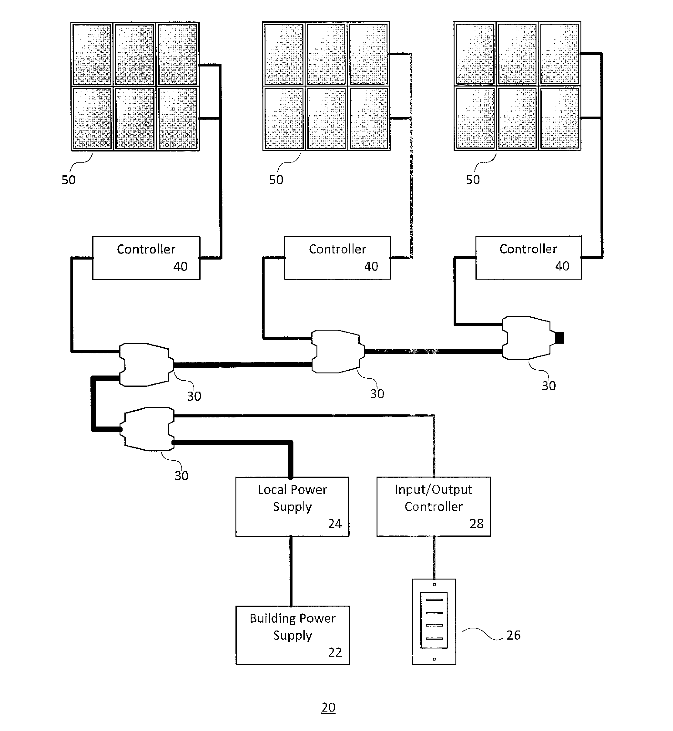
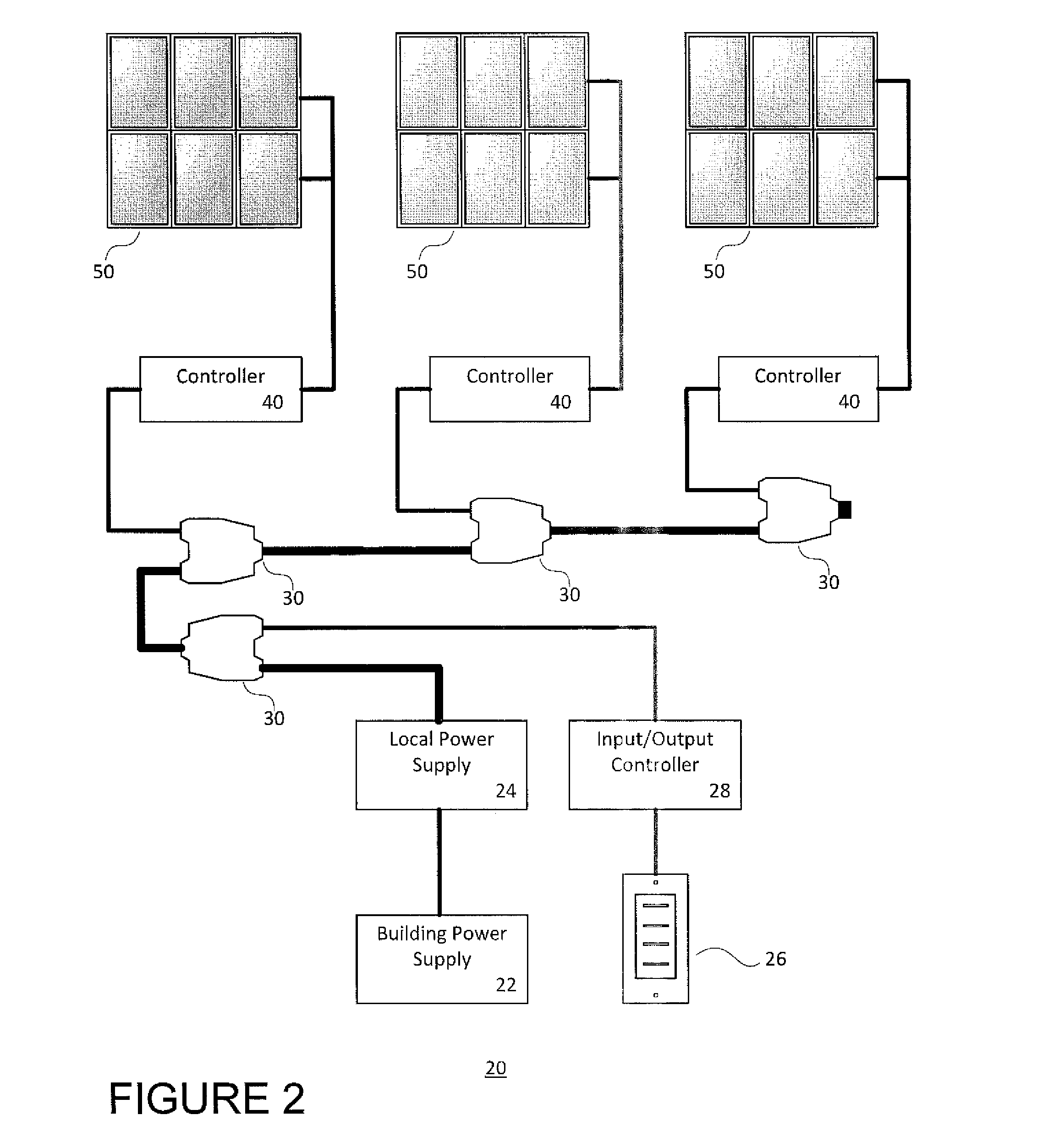
[0028]One object of the present invention is to provide an improved wiring architecture for powering a plurality of local window controllers that individually control the operation of a plurality of respective smart windows. The improved architecture permits installation of multiple controllers for smart windows having an electrical designation other than a Class 1 designation (e.g., having a “Class 2” designation). This reduces costs associated with the parts and installation (e.g., technique, labor) of the wiring architecture. Specifically, the disclosed improved wiring architecture includes a plurality of individual controllers that are linked via communication lines (e.g., Ethernet cable). The individual controllers are also connected to a plurality of power sources in order to reduce the power requirements for any single power source.

[0029]Another object of the present invention is to provide a method of wiring the improved wiring architecture. Because the improved architecture...


PUM

PropertyMeasurementUnit
Lengthaaaaaaaaaa
Lengthaaaaaaaaaa
Poweraaaaaaaaaa

Abstract

The present disclosure relates generally to a wiring system for controlling one or more smart windows located within a building, and methods for installing such systems and/or replacing higher wattage systems with such systems.

Description

BACKGROUND OF THE INVENTION[0001]The present invention relates to a control system wiring architecture for controlling smart windows, and methods and techniques for wiring such architectures.[0002]As described in U.S. Pat. No. 7,710,671, the disclosure of which is hereby incorporated in its entirety herein, smart windows are glazing units that incorporate devices which have controllable optical and thermal transmission properties. The devices are generally in the form of layers either directly deposited on, or laminated to, the glass surface. Integration of the so-called smart windows into a building provides the opportunity to control internal light levels and temperature by adjusting the optical and thermal properties of the windows. Electrochromic devices, suspended particle devices (SPDs) polymer dispersed liquid crystal (PDLC), photovoltaic, and photochromic devices are all examples of devices that are incorporated in smart windows; light transmission in these particular device...

Claims


Application Information

Patent Timeline
IPC IPC(8): G02F1/163H01R43/26
CPCH01R43/26G02F1/163E06B9/24E06B2009/2464G05B15/02G05B2219/2642Y10T29/49117
Inventor GREER, BRYAN D.
Owner SAGE ELECTROCHROMICS
Why Eureka
Try Eureka