
Backlight module

a backlight module and module technology, applied in the field of backlight modules, can solve the problems of deteriorating and achieve the effect of improving the luminous efficacy of the luminous keyboard devi

Active Publication Date: 2014-12-18
PRIMAX ELECTRONICS LTD
View PDF2 Cites 34 Cited by
  • Summary
  • Abstract
  • Description
  • Claims
  • Application Information

AI Technical Summary

Benefits of technology

The present invention provides a backlight module that is not negatively affected by the adhesive used to bond the components together. The module includes a light-emitting element, a light guide plate, and a light shielding structure. The light shielding structure absorbs the light beam and prevents it from leaking out of the module. When the light beam is projected on the reflective material layer, a portion of it is reflected back into the light guide plate and another portion is transmitted through the reflective material layer and absorbed by the light shielding structure. Overall, the invention provides a more efficient and effective backlight module.

Problems solved by technology

Under this circumstance, the luminous efficacy of the luminous keyboard device is deteriorated.

Method used


Image

  • Backlight module
  • Backlight module
  • Backlight module

Examples


Embodiment Construction

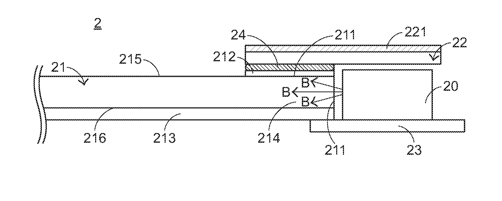
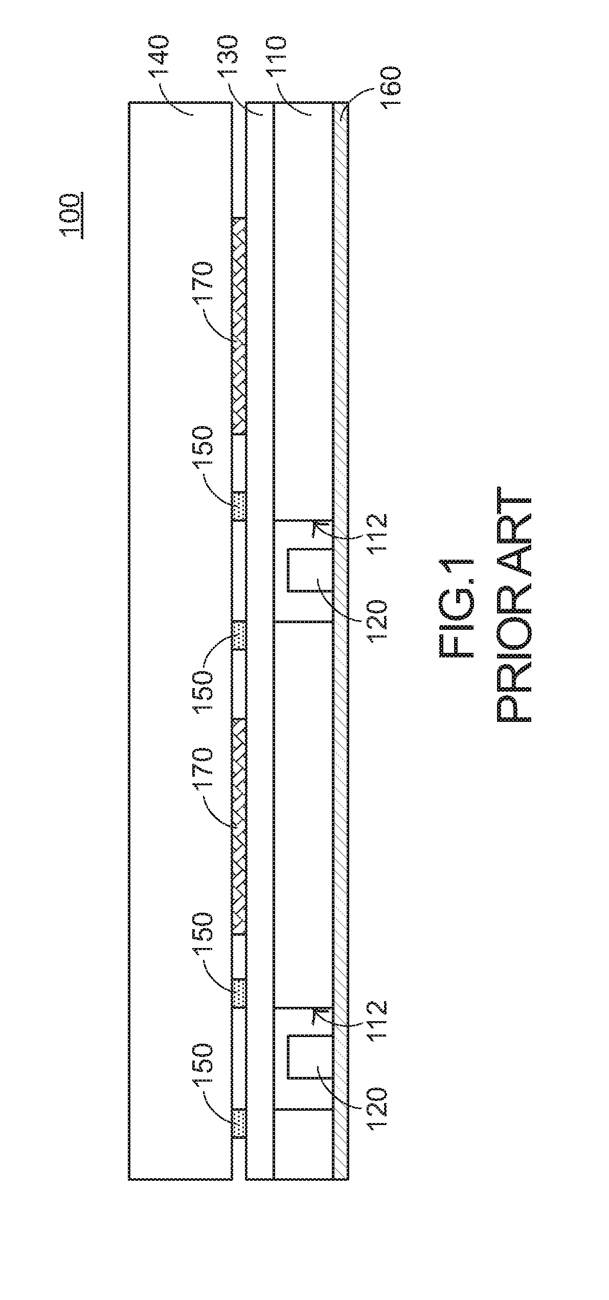
[0017]For eliminating the drawbacks encountered from the prior art technology, the present invention provides a backlight module. FIG. 3 is a schematic side view illustrating a backlight module according to a first embodiment of the present invention. As shown in FIG. 3, the backlight module 2 comprises plural light-emitting elements 20, a light guide plate 21, a light shielding structure 22, and an illumination circuit board 23. For clarification and brevity, only one light-emitting element 20 is shown in the drawing. The light guide plate 21 comprises a sidewall 211, a first reflective material layer 212, and a reflecting ink layer 213. The sidewall 211 is located at a lateral edge 214 of the light guide plate 21. The plural light-emitting elements 20 are located near the sidewall 211. The functions of the first reflective material layer 212 and the reflecting ink layer 213 will be described later. The illumination circuit board 23 is located beside the lateral edge 214 of the lig...


PUM


Abstract

A background module includes a light-emitting element, a light guide plate, and a light shielding structure. The light guide plate includes a reflective material layer. The reflective material layer is disposed on a top surface of the light guide plate and located near the light-emitting element. After a light beam emitted by the light-emitting element is introduced into the light shielding structure, a portion of the light beam is reflected back into the light shielding structure by the reflective material layer. On the other hand, a portion of the light beam is transmitted through the reflective material layer and absorbed by the light shielding structure. Consequently, the possibility of causing light leakage will be minimized.

Description

FIELD OF THE INVENTION[0001]The present invention relates to a backlight module, and more particularly to a backlight module for use in an electronic device.BACKGROUND OF THE INVENTION[0002]A backlight module is usually applied to a display device or a luminous input device. For example, most electronic devices are equipped with display devices for providing a prompting function. According to the contents shown on the display devices, the user may realize the current operating statuses of the electronic devices. Generally, a display device comprises a backlight module and a display panel. The backlight module is used for providing a light beam and guiding the light beam into the display panel. When the light beam is transmitted through the display panel, the corresponding content is shown on the display panel. On the other hand, the luminous input device comprises a backlight module and an input interface. The input interface is for example a keyboard device, a handwriting device or...

Claims


Application Information

Patent Timeline
IPC IPC(8): F21V8/00
CPCG02B6/0013G02B6/0021G02B6/0031G02B6/005G02B6/0055H01H13/83H01H2219/06H01H2219/062
Inventor CHEN, BO-ANHO, HSUAN-WEI
Owner PRIMAX ELECTRONICS LTD
Features
  • Generate Ideas
  • Intellectual Property
  • Life Sciences
  • Materials
  • Tech Scout
  • Unparalleled Data Quality
  • Higher Quality Content
  • 60% Fewer Hallucinations
Learn More