Automatic Floor Cleaner

a floor cleaner and automatic technology, applied in the field of floor cleaners, can solve the problems of reducing the effect of dust removal, increasing the workload of staff, and reducing the workload, so as to achieve the effect of cleaning more effectively

Inactive Publication Date: 2014-12-25
YEJEN APPLIANCES SHENZHEN
View PDF7 Cites 19 Cited by
  • Summary
  • Abstract
  • Description
  • Claims
  • Application Information

AI Technical Summary

Benefits of technology

[0007]Therefore, an objective of the present invention is to provide an automatic floor cleaner to improve the aforementioned shortcoming and deficiency of

Problems solved by technology

However, the manual way may increase the workload of the staff To reduce the workload, a mobile cleaning robot is disclosed in U.S. Pat. No. 6,938,298 B2, which employs a drive unit and a velcro system secured with a cleaning cloth to allow the robot to move across the floor in a random manner for removing dusts on the floor.
1. While cleaning t

Method used


Image

  • Automatic Floor Cleaner
  • Automatic Floor Cleaner
  • Automatic Floor Cleaner

Examples


first embodiment

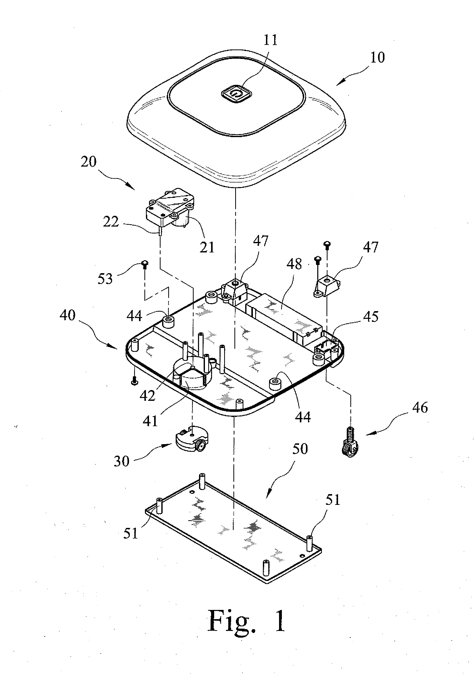
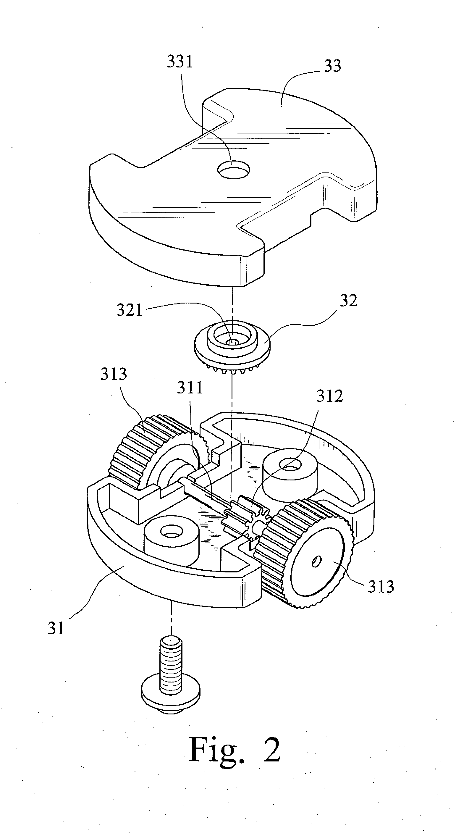
[0026]Referring to FIGS. 1 through 4, an automatic floor cleaner according to the present invention is shown, which generally includes a cover 10, a motive assembly 20, a driving wheel assembly 30, a base plate 40, and a flat bottom plate 50. The cover 10 can be affixed to the base plate 40 by using screws.

[0027]The cover 10, being generally rectangular in shape, is provided with an electrical switch 11 on its top surface for activating the floor cleaner to clean a floor surface. Other input devices can also be provided on the cover 10 for allowing a user to select the operation time. The base plate 40, being generally rectangular in shape, defines a first bottom space 41 near its front side. The first bottom space 41 is a recess for accommodating the driving wheel assembly 30. A through-hole 42 is defined in the base plate 40 over the first bottom space 41. There are two second bottom spaces 45 respectively defined near the right side and the left side of the base plate 40. The bas...

second embodiment

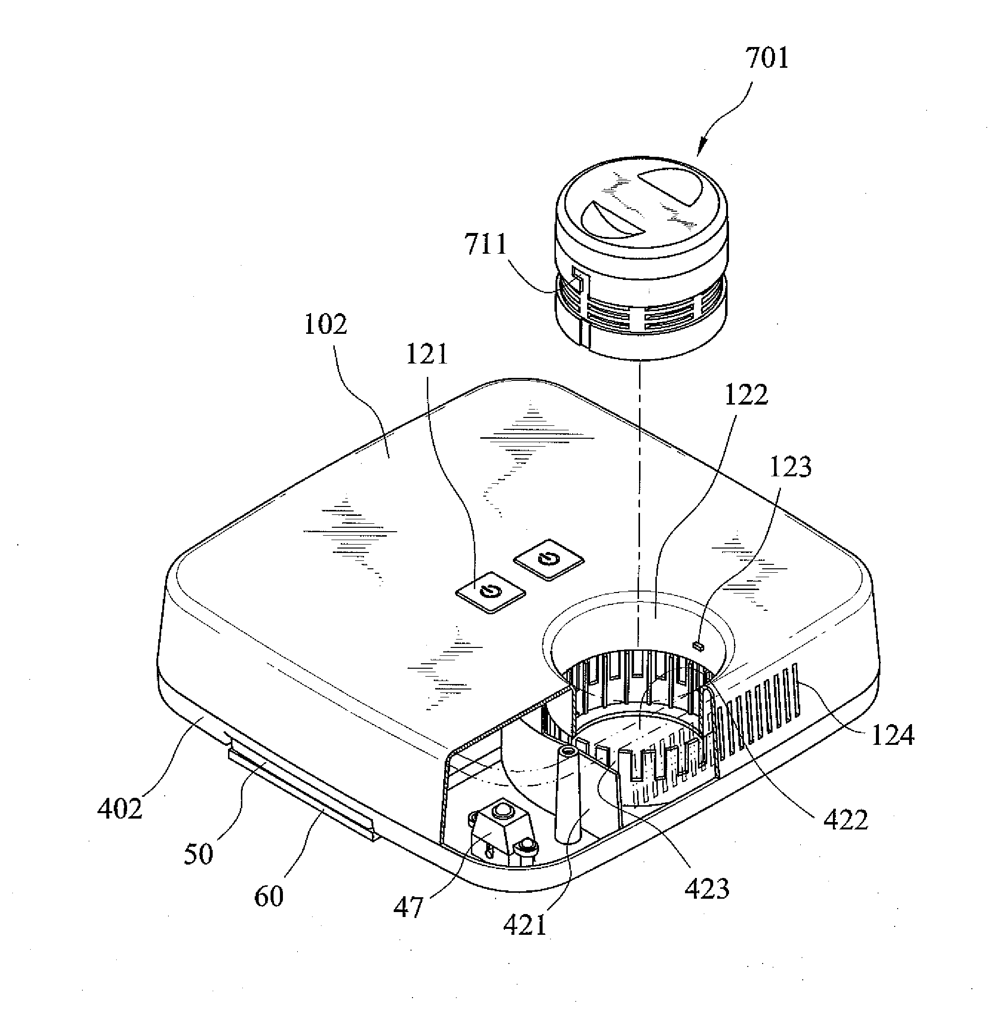
[0032]FIGS. 5 and 6 show the present invention. As shown, in addition to the cover 101, the base 401, the flat bottom plate 50, the dust removal sheet 60, the wheel caps 47, and the rear wheel assemblies 46, the floor cleaner further includes a vacuum cleaning unit 70, which defines outtakes around its periphery and intakes in its bottom. Also, the vacuum cleaning unit 70 is provided with an engagement lug 71 at its periphery. The cover 101 is provided with an electrical switch 111 on its top surface. Furthermore, the cover 101 defines outlet ventilation openings 112 in one side thereof. The power supply 415 is provided on the base plate 401 above the flat bottom recess 431. The base plate 401 has an enclosed inner wall defining a third bottom space 412, being a recess, between the second bottom spaces 451 and defines inlet ventilation openings 414 around the enclosed inner wall and defines an attachment slot 413 in the enclosed inner wall. Furthermore, the base plate 401 is provide...

fourth embodiment

[0034]FIGS. 8 and 9 show the present invention, which is different from the previous embodiments in installing the vacuum cleaning unit. The vacuum cleaning unit 702 defines outtakes around its periphery and intakes at its bottom. Also, the vacuum cleaning unit 702 is provided with an attachment lug 721 at its periphery. The base plate 403 has an inwardly extending wall at a rear side thereof defining a third bottom space 432 with a side opening and defines inlet ventilation openings 433 around the inwardly extending wall and defines an attachment slot 434 in the inwardly extend wall. The base plate 403 is provided with a separation wall 431 around the inwardly extending wall. The cover 103 defines an entrance opening 132 corresponding to the side opening of the third bottom space 432 and defines outlet ventilation openings 133 being adjacent to the entrance opening 132 and corresponding to the inlet ventilation openings 433 of the base plate 403. The vacuum cleaning unit 702 is det...


PUM


Abstract

An automatic floor cleaner includes a cover, a base plate, a motive assembly, a driving wheel assembly, and a flat bottom plate. In use, the flat bottom plate can be attached with a dust removal sheet to mop a floor surface. When the floor cleaner hits an object, the driving wheel assembly can rotate about a vertical output axle of the motive assembly to cause the moving direction of the floor cleaner to be changed to a randomly new direction, so that the floor cleaner can escape the object to continue advancing and cleaning the floor surface. Furthermore, the floor cleaner can be mounted with a vacuum cleaning unit, so that the cleaning effect can be improved.

Description

BACKGROUND OF THE INVENTION[0001]The present invention relates to a floor cleaner and, more particularly, to an automatic floor cleaner that can adjust its moving direction to continue the cleaning operation.[0002]Dusts or particles are often existed on the floor in a house or a workplace. Generally, they are removed by a manual way, such as using broom or a vacuum cleaner. However, the manual way may increase the workload of the staff To reduce the workload, a mobile cleaning robot is disclosed in U.S. Pat. No. 6,938,298 B2, which employs a drive unit and a velcro system secured with a cleaning cloth to allow the robot to move across the floor in a random manner for removing dusts on the floor. Since the cloth is flexible, when the robot moves to a wall, the cloth can be moved a small distance up the wall, so that the dusts in the corner between the floor and the wall can be removed. Also, the robot can be provided with a fan to have it become a movable vacuum cleaner.[0003]However...

Claims


Application Information

Patent Timeline
IPC IPC(8): A47L11/40A47L9/28
CPCA47L11/4061A47L9/2852A47L9/2857A47L9/009A47L9/0606A47L11/20A47L2201/00
Inventor HSU, PEI-CHENG
Owner YEJEN APPLIANCES SHENZHEN
Why Eureka
Try Eureka