Base Assembly for Floor Cleaner

Inactive Publication Date: 2014-12-25
HAAN GYUNG HEE
View PDF2 Cites 11 Cited by
  • Summary
  • Abstract
  • Description
  • Claims
  • Application Information

AI Technical Summary

Benefits of technology

[0021]Due to the configuration of the slope rails and slope wheels, it is possible to obtain a driving force to allow a pair of rag attachment pads to move oppositely to come close and go away from each other using a single driving member.
[0023]According to the present invention as described above, it is possible to achieve various effects as follows.
[0024]Because the steam distribution path is laid directly above the reciprocating pads, not only a floor wiping effect but also sterilization of floor can be achieved.
[0025]Especially, because the steam injection protrusions are formed in the distribution path, thereby being arranged above the steam passage holes, steam can be injected to rags and pads at a position very close to the rags or pads to such an extent that the steam can sufficiently permeate into the rags or pads.
[0026]As the slope rails are constituted by the slo

Problems solved by technology

However, the conventional floor cleaner has problems as follows.
As a result, the floor cleaner has restrictions in introducing the floor cleaner into a gap below a sofa, furniture, a bed, etc.
In addition, because the construction of the belt and pulleys is complicated, and the power conversion units are arranged to be space

Method used


Image

  • Base Assembly for Floor Cleaner
  • Base Assembly for Floor Cleaner
  • Base Assembly for Floor Cleaner

Examples


Embodiment Construction

[0037]Hereinbelow, an exemplary embodiment of the present invention will be described with reference to accompanying drawings.

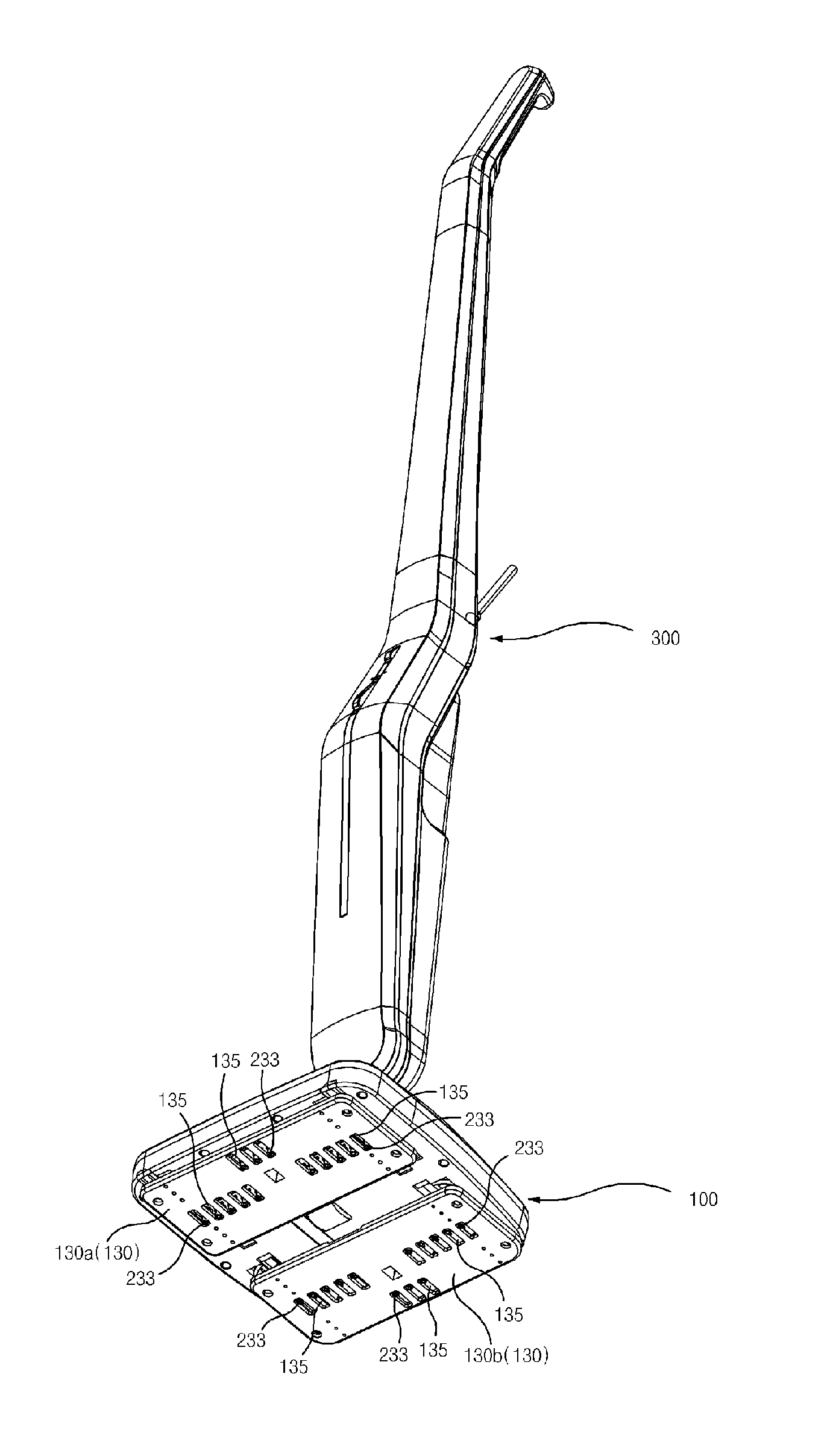
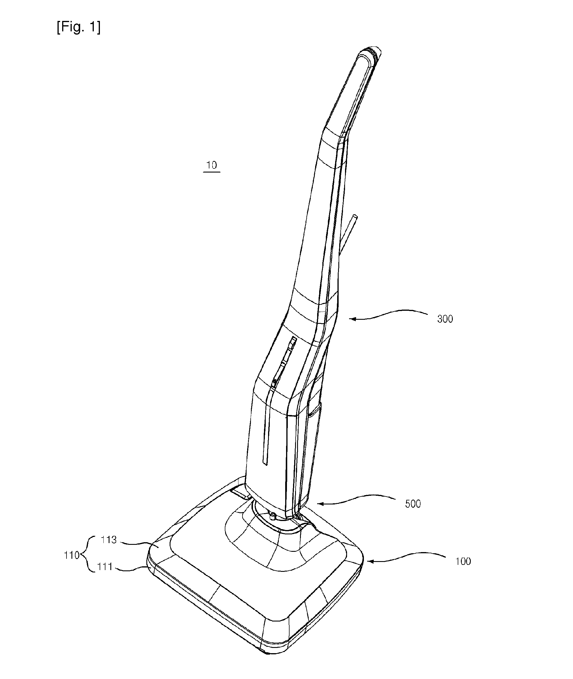
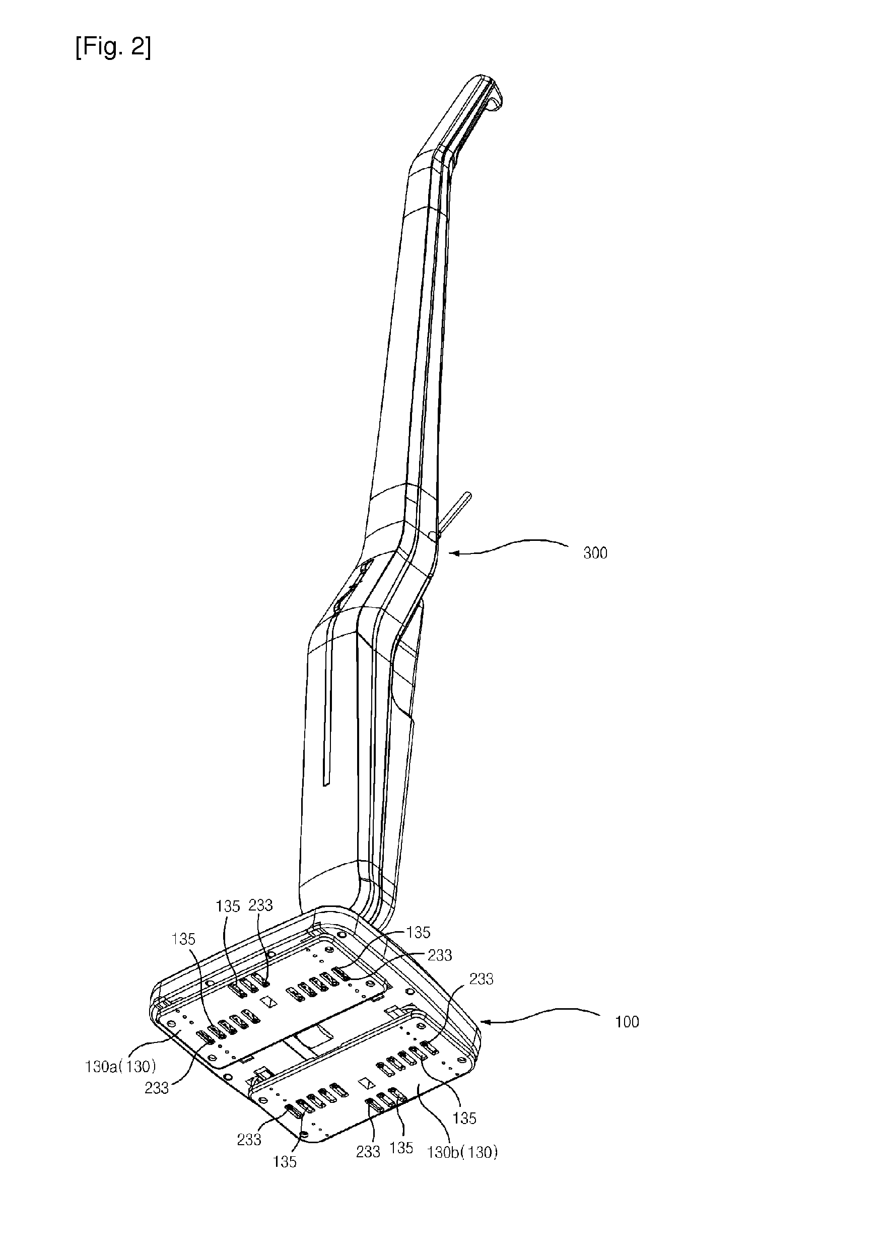
[0038]FIG. 1 is a front side perspective view illustrating a floor cleaner according to an exemplary embodiment of the present invention, FIG. 2 is a rear side perspective view of FIG. 1, and FIGS. 3 and 4 are front and rear side exploded perspective views illustrating a base assembly for the floor cleaner according to the exemplary embodiment of the present invention. In addition, FIGS. 5 and 6 are perspective views illustrating a principal part in assembled and disassembled states, respectively, FIG. 7 is a perspective view illustrating a driving member and a mounting case according to an exemplary embodiment of the present invention in a separated state, and FIG. 8 is a rear view of a base assembly for a floor cleaner according to an exemplary embodiment of the present invention. Moreover, FIG. 9 is a cross-sectional view taken along line q-q or line q-q o...


PUM


Abstract

The present invention relates to a base assembly for a floor cleaner configured to clean a floor through linear reciprocation movement of two rag attachment pads through which the two rag attachment pads come close to and go away from each other. More particularly, the present invention relates to a base assembly for a floor cleaner capable of simultaneously conducting cleaning and sterilization of a floor by injecting steam onto the rag attachment pads while the rag attachment pads are being reciprocally moved.

Description

TECHNICAL FIELD[0001]The present invention relates to a base assembly for a floor cleaner configured to clean a floor through linear reciprocation movement of two rag attachment pads through which the rag attachment pads come close to and go away from each other, and more particularly a base assembly for a floor cleaner capable of simultaneously conducting cleaning and sterilization of a floor by injecting steam onto the rag attachment pads while the rag attachment pads are being reciprocally moved.Background Art[0002]In the prior art, publications, for example, Patent Documents are presented that disclose floor cleaners configured to clean a floor by linearly reciprocating opposite rag attachment pads.[0003]A floor cleaner body disclosed in the Patent Documents includes: a support member; a driving unit positioned on the support member; power conversion units configured to convert rotating movement provided from the driving unit into linear reciprocation movement; first and second ...

Claims


Application Information

Patent Timeline
IPC IPC(8): A47L13/22
CPCA47L13/225A47L11/284A47L11/4036A47L11/4069A47L11/12
Inventor HAAN, GYUNG HEE
Owner HAAN GYUNG HEE
Why Eureka
Try Eureka