
Wearable mobile device charger

a technology for mobile devices and chargers, applied in the direction of portable computers, secondary cells servicing/maintenance, electrochemical generators, etc., can solve the problems of difficult continuous use of devices, people still often find the need to charge mobile devices, and use wired charging

Active Publication Date: 2014-12-25
SOL CUFF TECH
View PDF8 Cites 63 Cited by
  • Summary
  • Abstract
  • Description
  • Claims
  • Application Information

AI Technical Summary

Benefits of technology

This patent describes a wireless charging device that can be worn on a user's wrist. The device has components that collect ambient energy and convert it into electrical energy. The device also has components that store the electrical energy and transmit it to a mobile device to charge its battery. The technical effect of this invention is to provide a convenient and efficient way to charge mobile devices without the need for a wired connection.

Problems solved by technology

While battery technology is continuously being explored to provide longer batter lifes, people still often find the need to charge their mobile devices in situations where there is no easy charging means available.
Using wired charging may, however, be cumbersome and make continuous use of the device difficult.
While handheld flashlights are often used, these may occupy the officer's hand and thus, does not allow “hands free” light operation.
In addition, many lighting devices require charging or battery replacement.
These devices, however, fail to provide a lightweight, ambiently charged, wrist mounted illumination device that provides desirable directed light.
Additionally, these devices do not provide any means for charging a mobile device.

Method used


Image

  • Wearable mobile device charger
  • Wearable mobile device charger
  • Wearable mobile device charger

Examples


Embodiment Construction

[0019]In the context of this patent, the term “coupled” means either a direct connection or an indirect connection (e.g., one or more intervening connections) between one or more objects or components. The phrase “directly connected” means a direct connection between objects or components such that the objects or components are connected directly to each other so that the objects or components operate in a “point of use” manner.

[0020]In the context of this patent, the term “mobile device” refers to any wireless electronic device that utilizes mobile connection technology (e.g., cellular, satellite, or wireless technology). Examples of mobile devices include, but are not limited to, cellular phones, smart cellular phones, PDAs, computer tablets, GPS units, radios, mobile lighting solutions, and gaming devices.

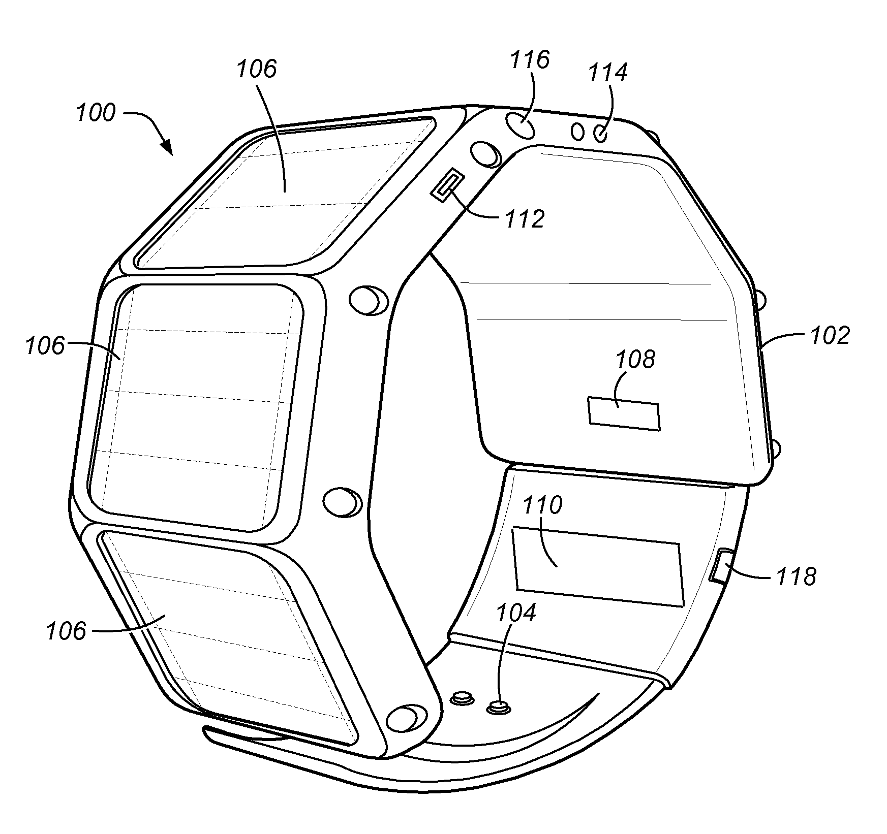
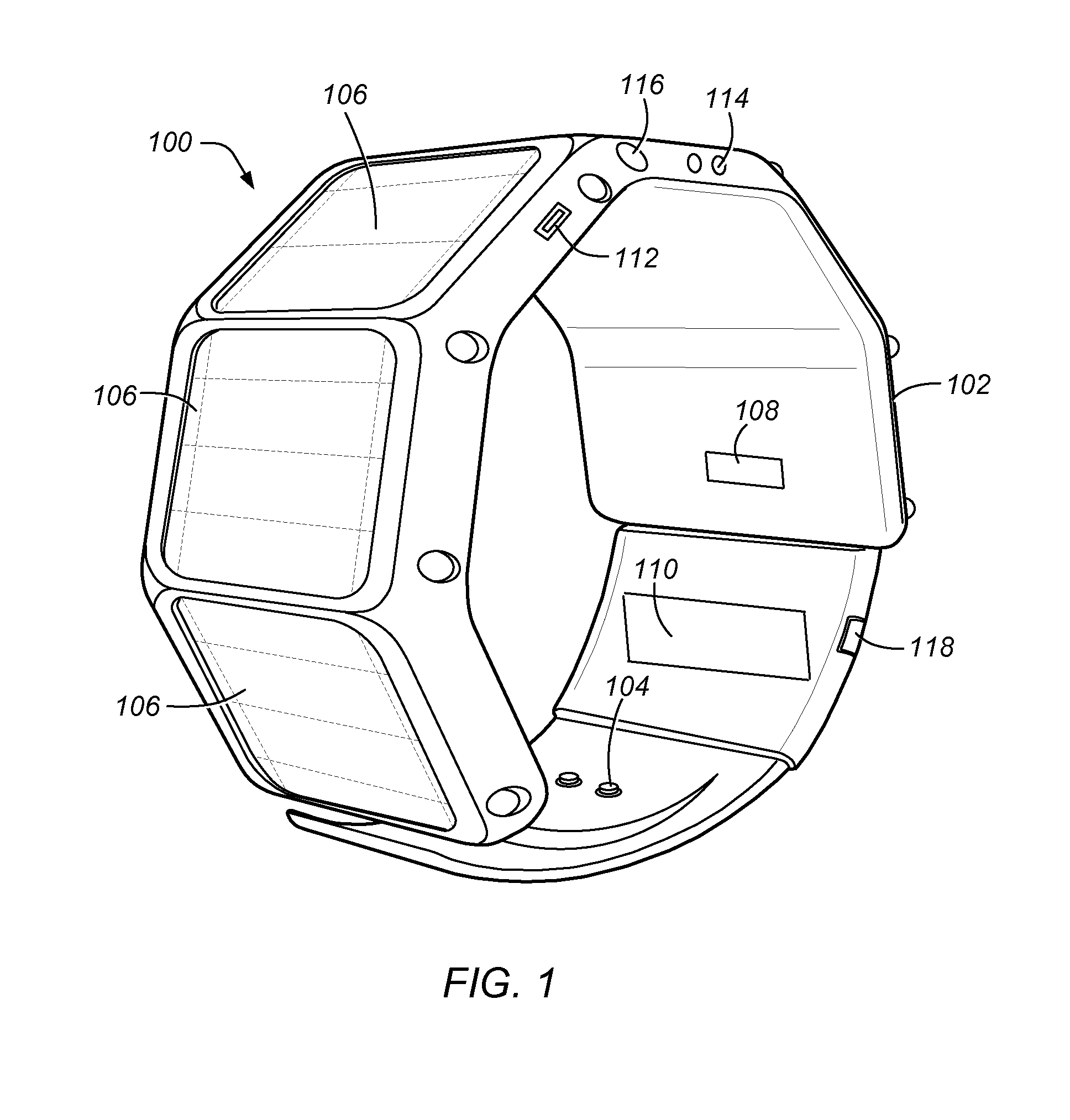
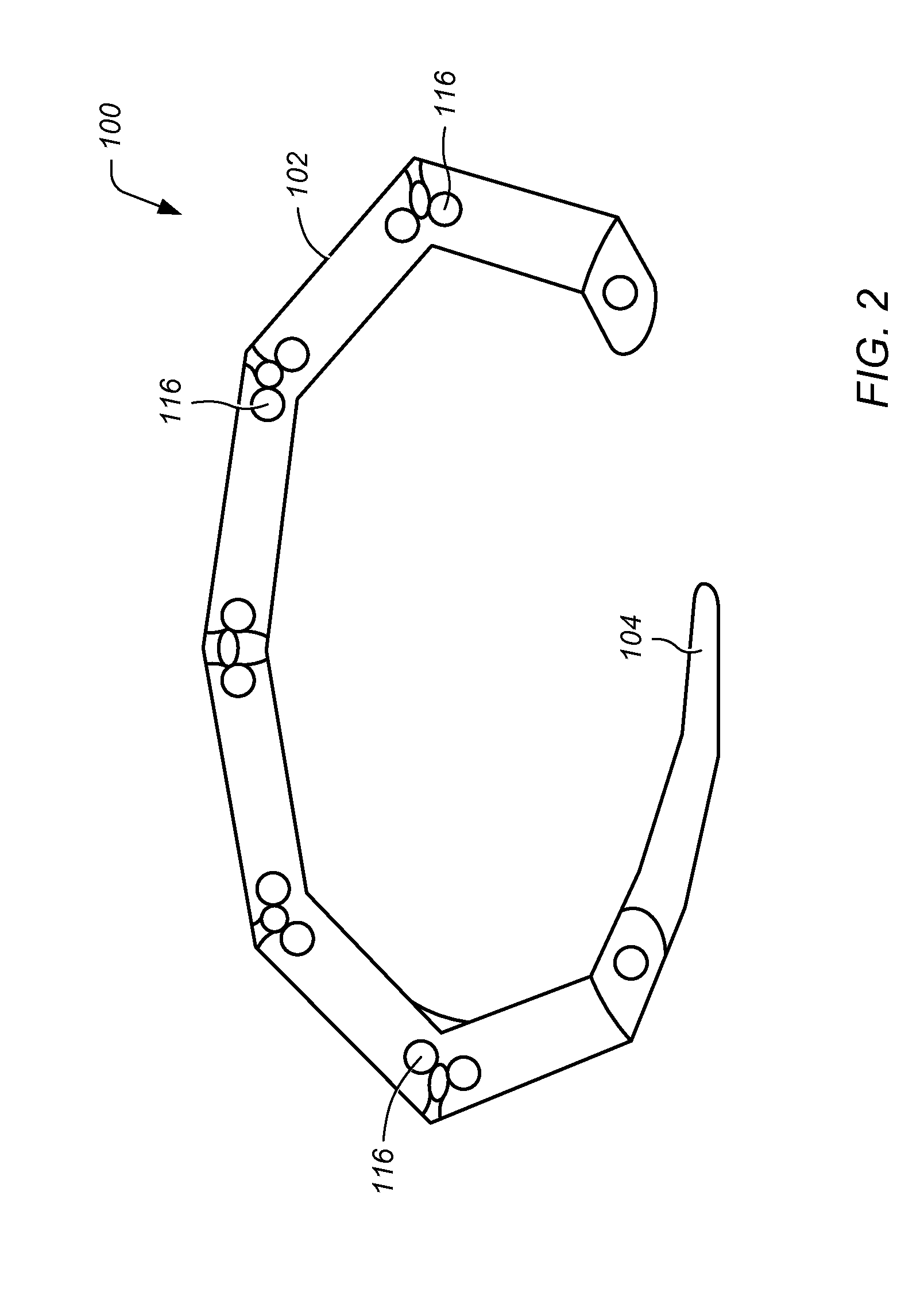
[0021]FIG. 1 depicts a perspective view of an embodiment of wireless charging device 100. FIG. 2 depicts a front end view of an embodiment of wireless charging device 100. In ce...


PUM


Abstract

A wireless charging device may be worn as a wristband wearable on a user's wrist. The device includes one or more energy collection components located on the wristband. The energy collection components may collect ambient energy and convert the ambient energy to electrical energy. One or more energy storage components located on the wristband and electrically coupled to the energy collection components may store at least some of the electrical energy from the energy collection components. One or more energy transmission components may be located on the wristband and electrically coupled to the energy collection components and the energy storage components. The energy transmission components may wirelessly couple with a mobile device to wirelessly transmit at least some of the collected electrical energy to the mobile device for charging a battery on the mobile device.

Description

PRIORITY CLAIM[0001]This patent application claims priority to U.S. Provisional Patent No. 61 / 837,177 entitled “WRIST MOUNTED SOLAR BATTERY CHARGER ILLUMINATION DEVICE” to Boysen III. filed on Jun. 20, 2013 and to U.S. Provisional Patent No. 61 / 929,105 entitled “WEARABLE WIRELESS ENERGY TRANSFER SOURCE” to Boysen III et al. filed on Jan. 19, 2014.BACKGROUND[0002]1. Field of the Invention[0003]The present invention relates to a wearable device for charging electronic devices. More particularly, the invention relates to a wearable device that converts ambient energy to electrical energy, stores the electrical energy, and wirelessly charges electronic devices in proximity to the wearable device using the stored electrical energy.[0004]2. Description of Related Art[0005]The ability to conveniently recharge a mobile device (e.g., wireless device) when needed has become more and more desirable as the popularity, usage, and sophistication of wireless devices increases. For example, users i...

Claims


Application Information

Patent Timeline
Patent Type & Authority Applications(United States)
IPC IPC(8): H02J7/02H02J7/35H02J7/00
CPCH02J7/025H02J7/0045H02J7/355H02J7/0054H02J7/0047H02J7/0042H02J7/345H02J7/342H02J7/35H02J50/005H02J7/0048H02J50/12H02J7/0044H02J50/001G06F1/163H04B5/79
Inventor BOYSEN, III, LAWRENCEVAUGHAN, MARK W.M.
Owner SOL CUFF TECH
Learn More