Map display device

a map and display device technology, applied in surveying and navigation, navigation instruments, instruments, etc., can solve the problems of large computation requirements and user inability to recognize the position of facilities, and achieve the effect of speeding up the comparing and determining process

Inactive Publication Date: 2014-12-25
MITSUBISHI ELECTRIC CORP
View PDF4 Cites 48 Cited by
  • Summary
  • Abstract
  • Description
  • Claims
  • Application Information

AI Technical Summary

Benefits of technology

[0011]According to the present invention, in the determination of whether or not a map object which constructs the map data is hidden behind another map object, the number of times that the comparing and determining process is performed can be suppressed, and the comparing and determining process can be speeded up.

Problems solved by technology

A problem is, however, that when a billboard process of expressing two-dimensional map data in three dimensions is performed, and a terrain undulation is expressed, a facility selected by the user is hidden behind the terrain undulation, and, as a result, the icon of the facility may not be displayed on the map display screen and only the detailed information about the facility may exist on the screen, so that the user cannot recognize the position of the facility which the user has selected.
A problem is that the comparing process on a per pixel basis is required of the occlusion culling using a Z buffer, and therefore the required amount of computations is large.

Method used


Image

  • Map display device
  • Map display device
  • Map display device

Examples


Embodiment Construction

[0025]Hereafter, in order to explain this invention in greater detail, the preferred embodiments of the present invention will be described with reference to the accompanying drawings. Embodiment 1.

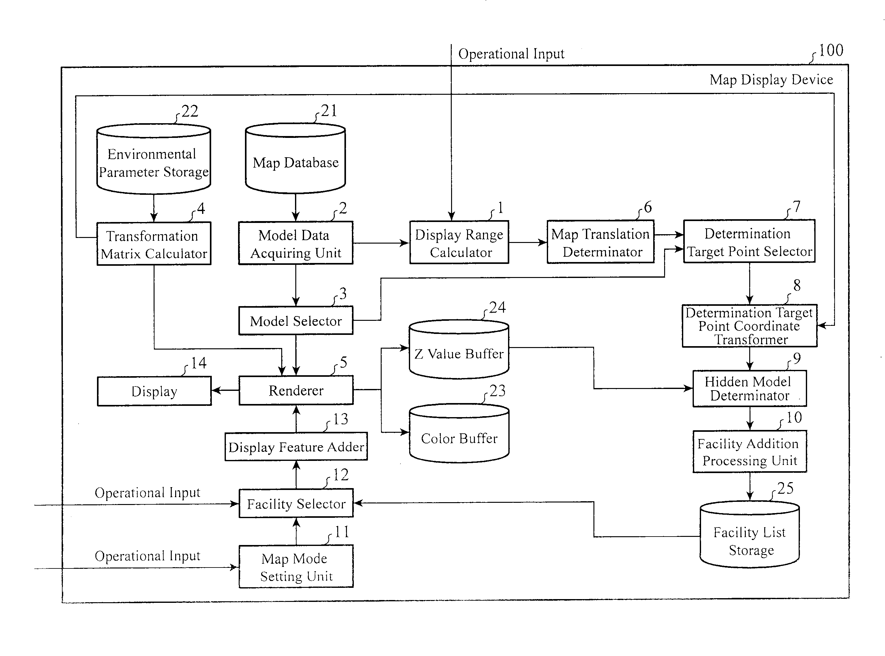
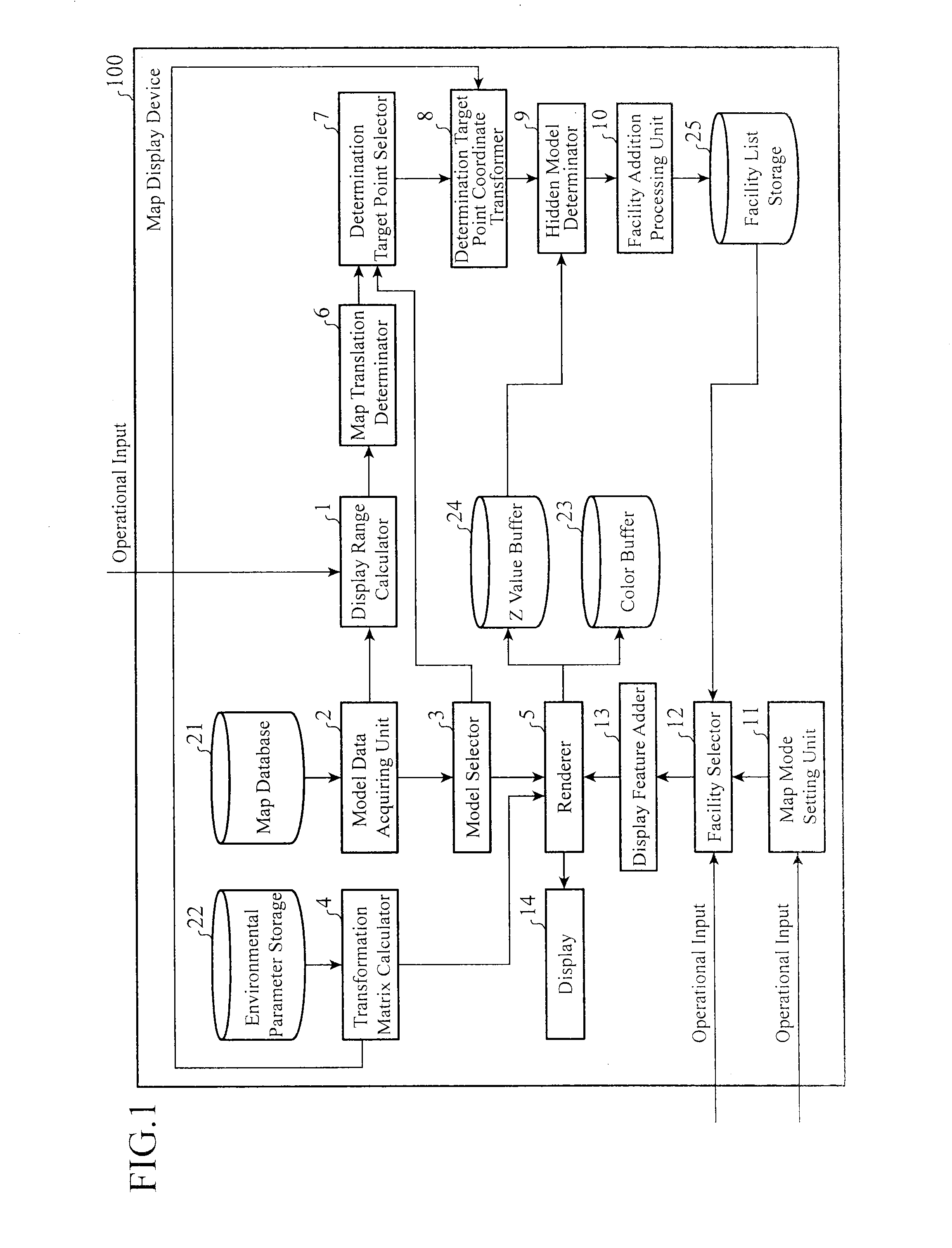
[0026]FIG. 1 is a block diagram showing the structure of a map display device in accordance with Embodiment 1 of the present invention. Referring to FIG. 1, the map display device 100 is comprised of a display range calculator 1, a model data acquiring unit (object information acquiring unit) 2, a model selector (object selector) 3, a transformation matrix calculator 4, a renderer 5, a map movement determinator 6, a determination target point selector 7, a determination target point coordinate transformer 8, a hidden determinator 9, a facility addition processing unit (storing processor) 10, a map mode setting unit 11, a facility selector (selector) 12, a display feature adder 13, and a display 14. The map display device further includes, as storage areas, a map database 21, an environmen...


PUM


Abstract

A hidden model determinator that compares a coordinate value in a depth direction which is acquired by performing a coordinate transformation on each of a first determination target point and a second determination target point which are selected from model data about a facility model with that in the depth direction of model data about a topographical model, which is stored in a Z value buffer, to determine whether or not the facility model is hidden behind the topographical model, and a facility addition processing unit that stores model data about a facility model which the hidden model determinator determines is not hidden behind the topographical model.

Description

FIELD OF THE INVENTION[0001]The present invention relates to a map display device having a function of searching for and displaying facilities located around a vehicle.BACKGROUND OF THE INVENTION[0002]In recent years, a map display application representing a navigation device has a function of searching for facilities located around a vehicle. At the time of searching for surrounding facilities, facilities, such as convenience stores, hospitals, and post offices, which are located around the vehicle, are displayed on a map as icons or the likes. The user is allowed to refer to the map on which icons showing facilities are displayed, and select a facility which he or she desires by using an input unit such as a facility selection button. The user can also make the device display detailed information about the selected facility, and so on. As a display example, a selected facility is clarified by enclosing the selected icon with a thick frame, and facility information is expressed by ...

Claims


Application Information

Patent Timeline
Patent Type & Authority Applications(United States)
IPC IPC(8): G06T17/05G06T15/40
CPCG06T17/05G06T15/40G01C21/3638
Inventor TOMARU, YOSHIHIROKUBOYAMA, SHOICHIRO
Owner MITSUBISHI ELECTRIC CORP
Why Eureka
Try Eureka