
Imaging apparatus and flicker reduction method

a technology of flicker reduction and imaging apparatus, which is applied in the field of imaging apparatus and flicker reduction methods, can solve the problems of inability to detect flicker in high-speed imaging mode, inability to perform appropriate correction, and rapid change of flicker components acquired by inter-frame dft processing, so as to reduce flicker and reduce flicker of video signals

Active Publication Date: 2014-12-25
JVC KENWOOD CORP A CORP OF JAPAN
View PDF10 Cites 18 Cited by
  • Summary
  • Abstract
  • Description
  • Claims
  • Application Information

AI Technical Summary

Benefits of technology

The present invention provides a method for reducing flicker of a video signal that is output from an image pickup element. The method includes performing line integration on a video signal in one horizontal line in one vertical synchronization period, calculating a normalized line integrated value, Discrete Fourier Transform on the normalized line integrated value, calculating information of a flicker component, and calculating a correction gain based on the information of the flicker component in two or more horizontal lines. The invention also provides an imaging apparatus and flicker reduction method that can effectively reduce flicker.

Problems solved by technology

If there is a moving object in a subject, a correction gain rapidly changes, and thus appropriate correction cannot be performed, likely causing destruction of a video.
Further, as the DFT processing is performed inside a frame, when there is no flicker component for one cycle inside one frame, it may not be possible to detect flicker in, for example, a high-speed imaging mode.
Therefore, as a flicker component detected by brightness of a subject differs even under the same flicker environment, appropriate correction may not be performed.
Further, when there is a moving object in the subject, a flicker component acquired by inter-frame DFT processing rapidly changes.
Accordingly, appropriate correction cannot be performed, likely causing destruction of a video.

Method used


Image

  • Imaging apparatus and flicker reduction method
  • Imaging apparatus and flicker reduction method
  • Imaging apparatus and flicker reduction method

Examples


first embodiment

(Entire Configuration)

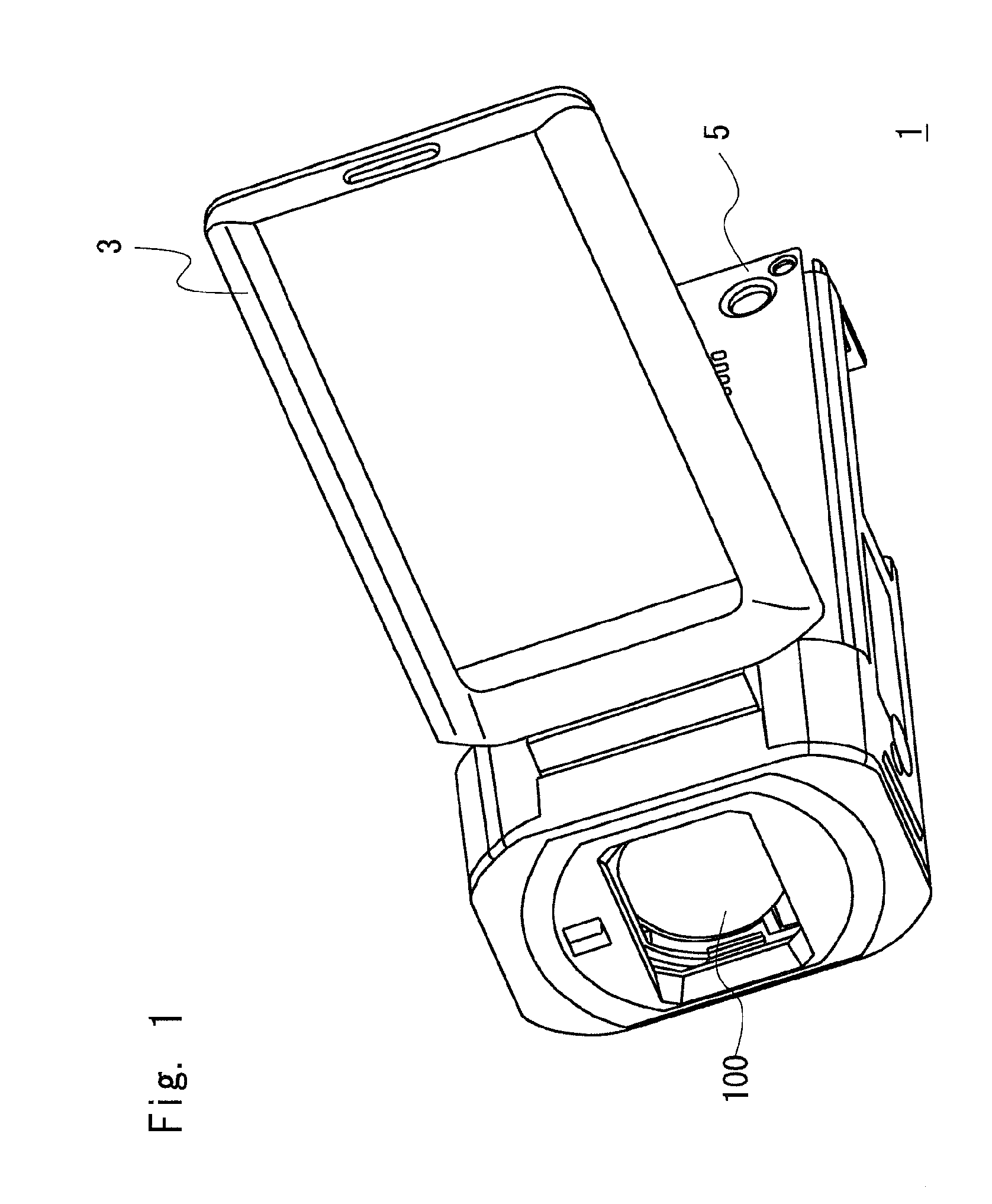
[0025]Hereinafter, an imaging apparatus and a flicker reduction method according to an embodiment of the present invention shall be explained with reference to the drawings. FIG. 1 is a perspective diagram showing an entire configuration of the imaging apparatus according to this embodiment. An imaging apparatus 1 includes a monitor 3, a housing 5, and an imaging unit 100.

[0026]The housing 5 includes the imaging unit 100 that is equipped with a CMOS image pickup element, a lens and the like. The imaging unit 100 receives light from a subject and images a moving image and a still image. Further, the housing 5 includes a battery, a built-in memory, a memory card slot, a CPU (Central Processing Unit) and the like that are not shown in the drawings. Predetermined processing is performed on image data obtained by the imaging unit 100, and the image data is stored to a memory. An openable and closable monitor 3 is attached to a side surface of the housing 5. The moni...

second embodiment

[0068]An imaging apparatus and a flicker reduction method according to this embodiment shall be explained using FIG. 6. FIG. 6 is a block diagram showing a part of a control system of the imaging apparatus 1. In this embodiment, in addition to the configuration of the first embodiment, an environment evaluation unit 130 for evaluating whether or not to perform the flicker correction is further provided. Note that an explanation of the overlapping elements in the configurations in the first and second embodiment shall be omitted as appropriate. For example, as the flicker component calculation processing by the flicker correction unit 107 is the same as the one in the first embodiment, an explanation of the flicker component calculation processing shall be omitted.

[0069]The environment evaluation unit 130 evaluates whether or not flicker is generated in a usage environment where the image apparatus 1 is used. That is, the environment evaluation unit 130 evaluates whether the usage en...

third embodiment

[0085]In this embodiment, by performing the DFT processing according to the flicker component that differs from frame rate to frame rate, the flicker correction in the high-speed imaging mode is realized. That is, in this embodiment, a function for performing the flicker correction in the high-speed imaging mode is further added to the configuration of the first or second embodiments.

[0086]For example, suppose that the frame rate of the image pickup element 104 is variable. When the frame rate of the image pickup element 104 changes, the flicker component of the video signal in one frame changes. When the frame rate is 60 fps, the flicker component for 5 / 3 cycle is included in one frame, as described above, while when the frame rate is 120 fps, the flicker component for 5 / 6 cycle is included in one frame.

[0087]FIG. 9 shows a comparison of the frame rate and flicker component when 60 fps is the normal imaging mode and 120 fps, which is a speed twice as fast as the normal imaging mode...


PUM


Abstract

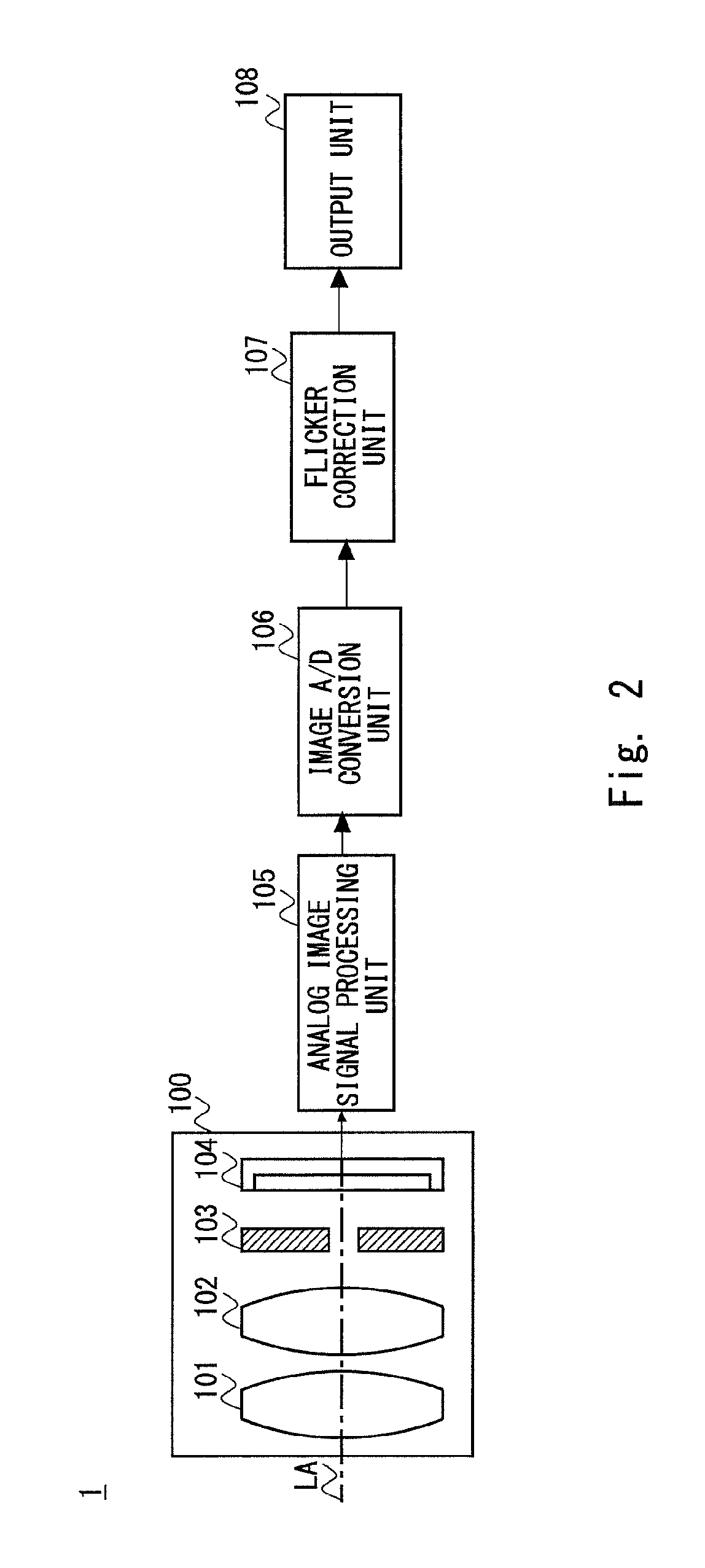
An imaging apparatus according to one embodiment of the present invention includes a flicker correction unit for correcting a flicker component using a correction gain. The flicker correction unit includes an integrating unit for calculating a line integrated value from a video signal in one horizontal line in one vertical synchronization period, a normalization unit for normalizing the line integrated value for a plurality of the vertical synchronization periods so as to calculate a normalized line integrated value, an inter-frame DFT processing unit for performing Discrete Fourier Transform on the normalized line integrated value for the plurality of vertical synchronization periods, a flicker component calculation unit for calculating information of a flicker component based on a Fourier Transform processing result, and a correction gain calculation unit for calculating a correction gain based on the information of the flicker component in two or more horizontal lines.

Description

INCORPORATION BY REFERENCE[0001]This application is based upon and claims the benefit of priority from Japanese patent application No. 2013-129416, filed on Jun. 20, 2013, the disclosure of which is incorporated herein in its entirety by reference.BACKGROUND OF THE INVENTION[0002]1. Field of the Invention[0003]The present invention relates to an imaging apparatus and a flicker reduction method.[0004]2. Description of Related Art[0005]Japanese Unexamined Patent Application Publication No. 2004-222228 and International Patent Publication No. WO2010 / 058567 disclose a reduction method of CMOS (Complementary Metal Oxide Semiconductor) flicker. In the flicker reduction method of Japanese Unexamined Patent Application Publication No. 2004-222228, a flicker reduction unit calculates an average value of integrated values of three consecutive fields and normalizes the integrated values by the average value. Then, the flicker reduction unit performs DFT (Discrete Fourier Transform) on the norm...

Claims


Application Information

Patent Timeline
IPC IPC(8): H04N5/235H04N23/76
CPCH04N5/2357H04N23/745
Inventor SHIMOOZONO, AKIHITOMATSUOKA, KENJI
Owner JVC KENWOOD CORP A CORP OF JAPAN
Learn More