

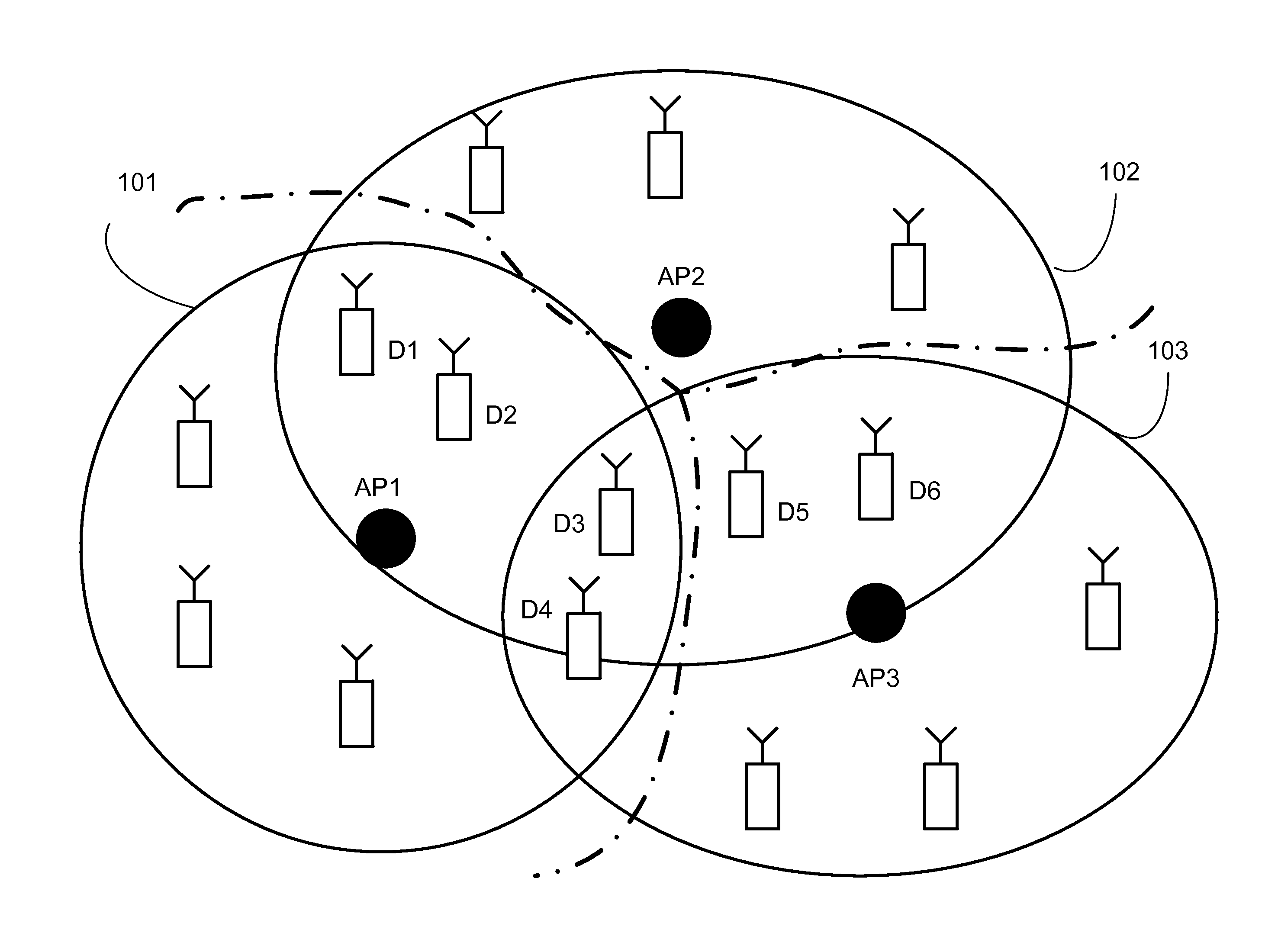
System and method for optimizing signal quality in a WIFI network
a technology of signal quality and wifi network, applied in the direction of wireless commuication services, network topologies, electrical appliances, etc., can solve the problems of difficult to predict the strength of wifi signal in a given area in relation to a transmitter, the line of sight between a transmitter and a receiver involved in the communication becomes blocked or shadowed, and the range of wifi networks is generally limited
- Summary
- Abstract
- Description
- Claims
- Application Information
AI Technical Summary
Benefits of technology
Problems solved by technology
Method used
Image

Examples
first embodiment
[0025]FIG. 4 is a flowchart illustrating a process for optimizing the signal quality for the devices in a cell covered by one access point, according to the Each of the access points of the WiFi network is configured to be implemented with the MCD software for the individual signal optimization, and the process illustrated in FIG. 4 represents one of them in the WiFi network. In the example of FIG. 4, the access point is configured to have a modal antenna designed to have N different modes, i.e., N different radiation patterns. First, a metric termed estimated downlink channel quality indicator (EDL-CQI) is defined for each device in the cell to characterize the signal quality in the uplink. The EDL-CQI is generated by taking into account the following properties associated with the link between the access point and each device: SNR that the access point can detect in the uplink (UL-SNR), and the modulation scheme in the downlink (DL-mod). The quality of signals in the downlink is ...
second embodiment
[0027]FIG. 5 is a flowchart illustrating a process for optimizing the signal quality for the devices in cells covered by two access points, according to the As is obvious to those skilled in the art, this process involving two access points can be extended to the case with three or more access points. These access points, AP1 and AP2, are configured to have respective modal antennas and communicate with each other. The AP1 has a modal antenna with N1 different modes, and the AP2 has a modal antenna with N2 different modes. In step 504, the AP1 informs the AP2 of the current mode i1 of the modal antenna of the AP1, where 1≦i1≦N1. In step 508, the estimated downlink CQI metric associated with the AP2, labeled EDL-CQI-2, is obtained for each device, (EDL-CQI-2)1, (EDL-CQI-2)2, . . . and (EDL-CQI-2)M2, where M2 is the number of devices in the cell covered by the mode i2 of the modal antenna of the AP2 while the AP1 is in the mode i1. In step 512, the cell quality indicator associated w...
PUM
 Abstract
Description
Claims
Application Information