Audio source position estimation

a technology for audio sources and positions, applied in direction finders, mouthpieces/microphone attachments, instruments, etc., can solve problems such as insufficient high practicability, and inability to provide sufficient information about the direction of the sour

Active Publication Date: 2014-12-25
KONINKLJIJKE PHILIPS NV
View PDF3 Cites 15 Cited by
  • Summary
  • Abstract
  • Description
  • Claims
  • Application Information

AI Technical Summary

Benefits of technology

[0045]According to an aspect of the invention, there is provided an apparatus for determining from a first microphone signal from a first microphone and a second microphone signal from a second microphone a position estimate for an audio source in an audio environment comprising an acoustic element providing an acoustic effect to sound from sound source positions to the first microphone, the acoustic effect being asymmetric with respect to an axis between the first microphone and the second microphone; the apparatus comprising: a first receiver for receiving the first microphone signal; a second receiver for receiving the second microphone signal; a first position circuit for estimating a first possible position and a second possible position for a sound source in response to time of arrivals at the first microphone and the second microphone for audio from the sound source, the first possible position being a position in a first area on one side of the axis and the second possible position being a position in a second area on an opposite side of the axis; an estimator for determining an acoustic effect measure for the first microphone signal, the acoustic effect measure being indicative of a degree to which an acoustic effect of the first microphone signal matches an expected characteristic of the acoustic effect for sound sources in the first area; a second position circuit for determining a position estimate for the sound source by selecting between the first possible position and the second possible position in response to the acoustic effect measure.
[0046]According to an aspect of the invention, there is provided a method for determining from a first microphone signal from a first microphone and a second microphone signal from a second microphone a position estimate for an audio source in an audio environment comprising an acoustic element providing an acoustic effect to sound from sound source positions to the first microphone, the acoustic effect being asymmetric with respect to an axis between the first microphone and the second microphone; the method comprising: receiving the first microphone signal; receiving the second microphone signal; estimating a first possible position and a second possible position for a sound source in response to time of arrivals at the first microphone and the second microphone for audio from the sound source, the first possible position being a position in a first area on one side of the axis and the second possible position being a position in a second area on an opposite side of the axis; determining an acoustic effect measure for the first microphone signal, the acoustic effect measure being indicative of a degree to which an acoustic effect of the first microphone signal matches an expected characteristic of the acoustic effect for sound sources in the first area; and determining the position estimate for the sound source by selecting between the first possible position and the second possible position in response to the first acoustic effect measure.

Problems solved by technology

This is typically highly impractical and therefore position determination is typically based on the difference in time of arrival measurements between the microphones.
However, another problem with a two microphone setup is that it is completely symmetric around the axis interconnecting the two microphones as illustrated in FIG. 1.
However, this approach has an inherent ambiguity and can only determine A in the range [0,180°].
Thus, it does not provide sufficient information about the direction of the source in the 360-degree azimuthal plane.
Specifically, it cannot differentiate between whether the sound source is located at position S or at the phantom position G.

Method used


Image

  • Audio source position estimation
  • Audio source position estimation
  • Audio source position estimation

Examples


Embodiment Construction

[0058]The following description focuses on embodiments of the invention applicable to position estimation from a sound source using Time Difference Of Arrival (TDOA) at only two microphones to determine an angular direction towards the audio source. However, it will be appreciated that the invention is not limited to this application but may be applied to many other applications determining positions of sound sources.

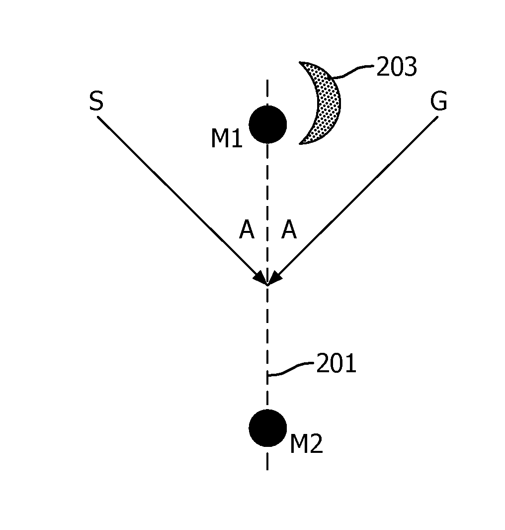
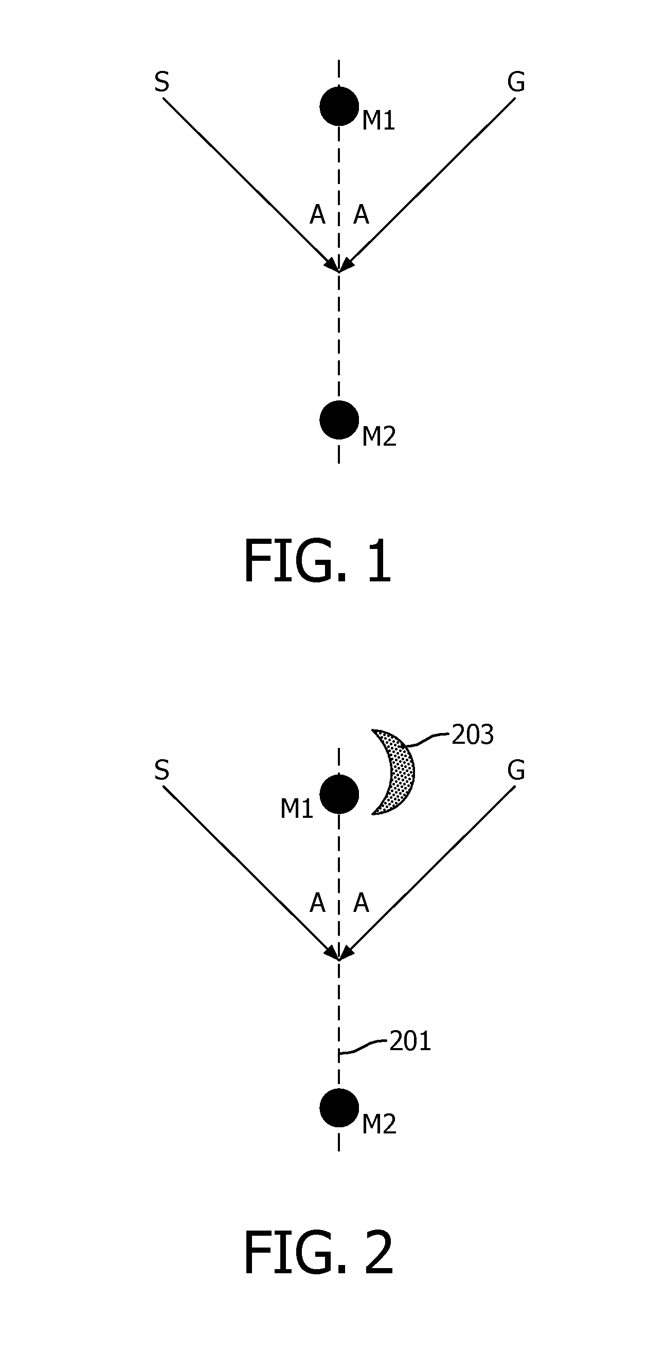
[0059]FIG. 2 illustrates an example of the configuration of the setup for the approach. Similarly to FIG. 1, the system employs two microphones M1 and M2 which are located with a given distance to each other. In the described approaches, a time difference of arrival of the sound from a sound source S to the two microphones M1 and M2 is used to first generate two possible positions. In particular, a first possible position in the half-plane to the left of the axis 201 between the microphones M1, M2 is generated and a second possible position in the half-plane to the righ...


PUM


Abstract

An apparatus for determining a position estimate for an audio source comprises two microphones (M1, M2) and an acoustic element (203) providing an acoustic effect to sound from sound source positions to the first microphone (M1). The acoustic effect is asymmetric with respect to an axis (201) between the microphones (M1, M2). A position circuit (305) estimates two possible positions on different sides of the axis for the sound source in response to time of arrivals at the microphones (M1, M2). An estimator (307) determines an acoustic effect measure being indicative of a degree to which an acoustic effect of the first microphone signal matches an expected characteristic of the acoustic effect for sound sources on one side of the axis (201). Another circuit (309) determines the position estimate by selecting between the two possible positions in response to the acoustic effect measure. The approach may resolve ambiguities in position determination associated with position determination based on time of arrival at two microphones.

Description

FIELD OF THE INVENTION[0001]The invention relates to position determination for an audio source, and in particular, but not exclusively, to position estimation based on time difference of arrival for signals at two microphones.BACKGROUND OF THE INVENTION[0002]In many applications knowledge of the position of an audio source is beneficial and may e.g. be used to optimize the signal processing of audio captured from the audio source. For example, the signal processing for hands-free communication and teleconferencing applications may be optimized dependent on the specific position, and typically just the angular direction, of the sound source. Accordingly, many audio processing systems comprise audio tracking systems that allow the (e.g. angular) position of a sound source to be detected and tracked.[0003]One approach for determining a position of an audio source uses a microphone array with the relative differences between the microphone signals being analyzed to estimate the positio...

Claims


Application Information

Patent Timeline
Patent Type & Authority Applications(United States)
IPC IPC(8): H04R3/00H04R1/08
CPCH04R1/08H04R3/005G01S3/8083G10K11/20H04R1/34H04R1/406H04R2430/20H04R3/00
Inventor KECHICHIAN, PATRICKOUWELTJES, OKKE
Owner KONINKLJIJKE PHILIPS NV
Why Eureka
Try Eureka