Apparatus and Process for De-Airing Material in an Extruder
What is AI technical title?
AI technical title is built by Patsnap AI team. It summarizes the technical point description of the patent document.
a technology of extruder and material, which is applied in the field of apparatus and process for de-airing material in an extruder, can solve the problems of affecting the proper processing of materials in the extruder, the tendency to plug the opening in the barrel, and the inability to use high viscosity materials in standard extruder arrangements that include venting systems
Active Publication Date: 2014-12-25
THE BONNOT
View PDF0 Cites 4 Cited by
Summary
Abstract
Description
Claims
Application Information
AI Technical Summary
This helps you quickly interpret patents by identifying the three key elements:
Problems solved by technology
Method used
Benefits of technology
Benefits of technology
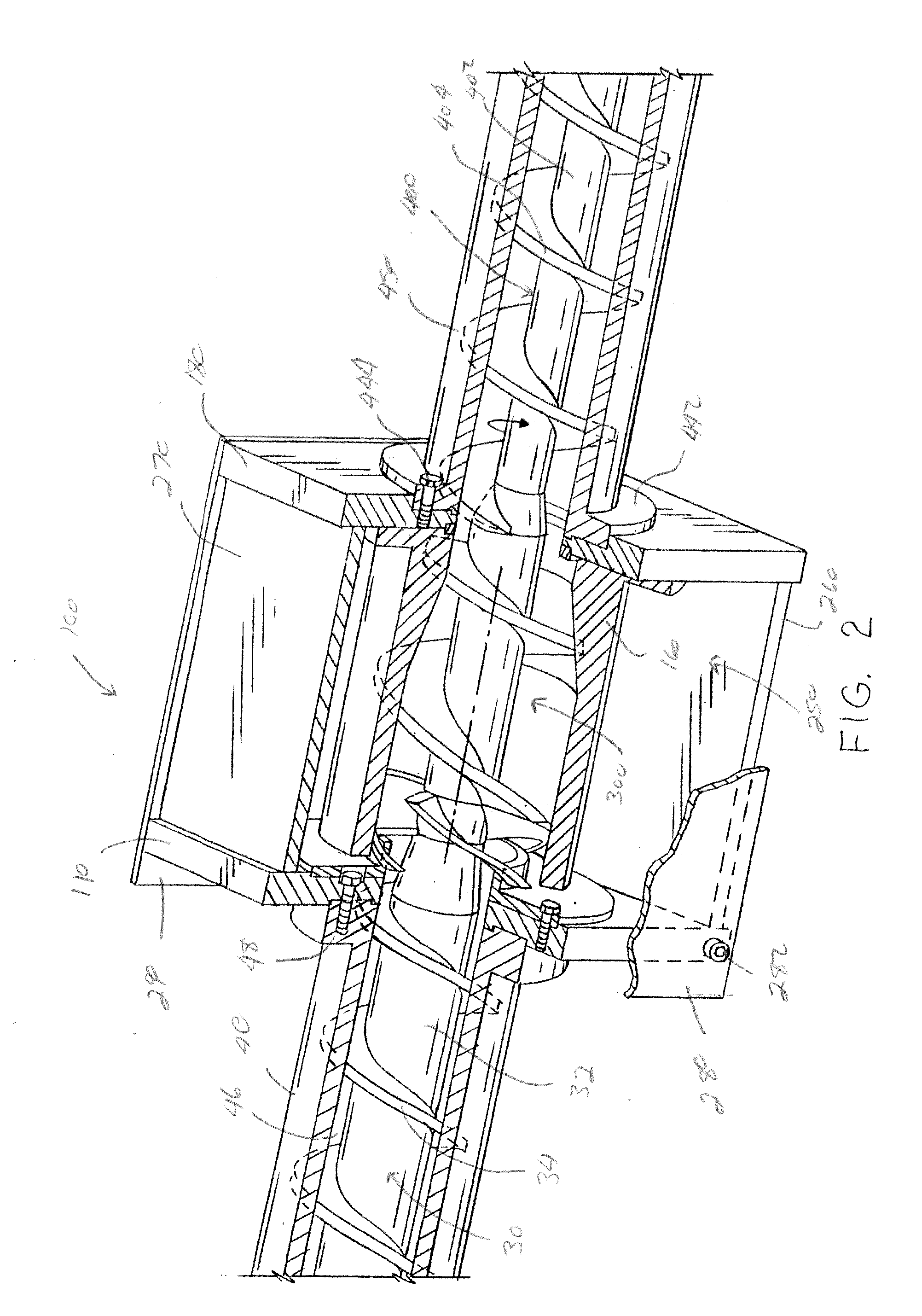
[0010]In yet another and / or alternative non-limiting aspect of the invention, the improved extruder arrangement of the present invention includes a vent block that has a vent cavity and / or screw element that are designed to cause a pressure drop as material is fed into the vent cavity; however, this is not required. The pressure drop is designed to limit or prevent material from flowing into the one or more gaps or openings in the vent cavity that are used to pull a vacuum on the vent cavity. The creation of a pressure drop can be achieved in one or more ways, such as, but not limited to, 1) creating a portion of the vent cavity having a larger cross-section size to the cross-section size of the opening in the inner feed ring, 2) reducing the root portion of the screw element as compared to the root of the auger or screw feeding material into the vent block, and / or 3) increasing the pitch of the one or more flights on the screw element as compared to the flight pitch of the auger or screw feeding material into the vent block.
[0013]It is one non-limiting object of the present invention to provide an extruder arrangement that can remove gas from material that is being fed through the extruder.
[0015]It is still another and / or alternative non-limiting object of the present invention to provide an extruder arrangement that includes a vent block having an inner feed ring and an outer ring and which rings are used to enable gas to be removed from a vent cavity while material is fed through the vent cavity and to inhibit or prevent material from moving into and / or clogging one or more gaps or openings that are used to remove gas from the vent cavity.
[0016]It is yet another and / or alternative non-limiting object of the present invention to provide an extruder arrangement that includes a vent block that includes a screw element having one or more fingers that are used to inhibit or prevent material from moving into and / or clogging one or more gaps or openings that are used to remove gas from the vent cavity.
Problems solved by technology
The entrapped air and / or other types of gasses can interfere with the proper processing of the materials in the extruder.
It has been found that materials that are more viscous than polymers, such as clays, mastics, ceramics and the like have a tendency to plug the opening in the barrel even when a diverter is used.
As such, standard extruder arrangements that include a venting system cannot be used with highly viscous materials.
Method used
Image
Click on the blue label to locate the original text in one second.
Reading with bidirectional positioning of images and text.
Examples
Embodiment Construction
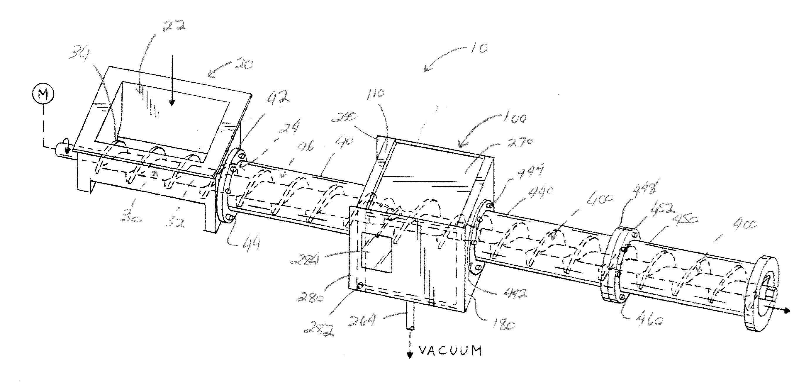
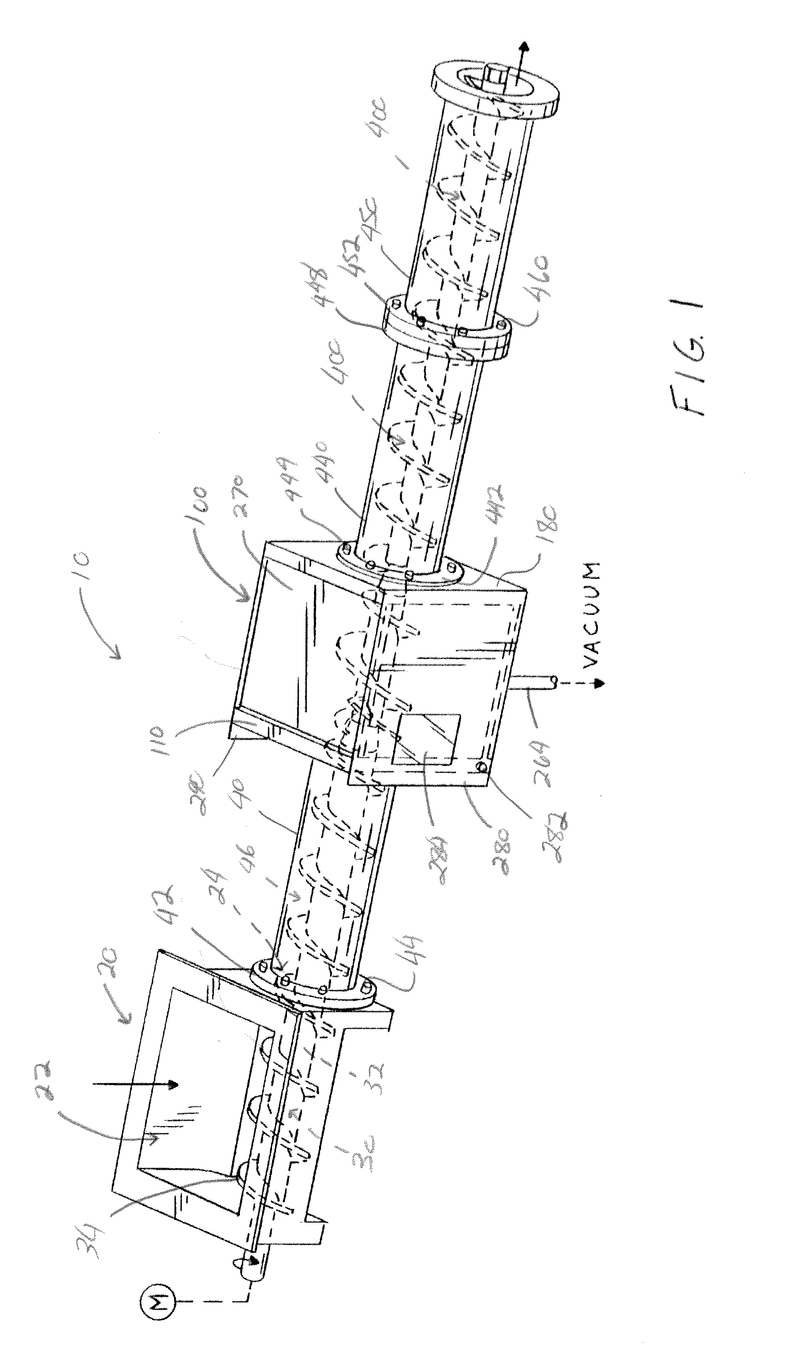
[0025]Referring now to the drawings wherein the showings are for the purpose of illustrating one non-limiting embodiment of the invention only and not for the purpose of limiting same, FIGS. 1-4 illustrate one non-limiting embodiment of the extruder arrangement in accordance with the present invention. The extruder arrangement 10 is designed to remove one or more gasses (e.g., air, nitrogen, water vapor, volatiles, etc.) from the material being feed through the extruder arrangement. The one or more gasses can create gas bubbles in the final product and / or interfere with the proper extrusion of the final product, thus compromising the integrity and / or quality of the final product extruded from the extruder arrangement. The extruder arrangement 10 is particularly useful in the extrusion of highly viscous materials (e.g., clay materials, etc.) and will be described with particular reference thereto; however, it will be appreciated that materials that are not highly viscous can also be ...
PUM
Property
Measurement
Unit
viscosity
aaaaa
aaaaa
size
aaaaa
aaaaa
length
aaaaa
aaaaa
Abstract
An extruder for feeding material and for removing gas from the fed material. The extruder includes a vent block positioned between a first and second auger. The vent block including a vent cavity having a feed end and an exit end, an inner feed ring that partially extends into said vent cavity at the feed end of the vent cavity, and a screw element rotatably positioned in the vent cavity. A front portion of the outer ring is longitudinally aligned with or overlapping the front end of the inner feed ring. The outer ring forms at least one gap or opening at or adjacent the feed end of the vent cavity to enable a vacuum to be pulled on the vent cavity as material is moved though the vent cavity from the feed end to the exit end by the screw element.
Description
[0001]The present invention is a divisional of U.S. application Ser. No. 13 / 306,368 filed Nov. 29, 2011, which in turn claims priority on U.S. Provisional Application Ser. No. 61 / 418,631 filed Dec. 1, 2010, which is fully incorporated herein by reference.[0002]The present invention is a device used to remove gas and / or moisture from a material being processed by an extruder.BACKGROUND OF THE INVENTION[0003]Many types of materials that are processed in an extruder can include entrapped air and / or other types of gasses. The entrapped air and / or other types of gasses can interfere with the proper processing of the materials in the extruder. Various arrangements have been developed to remove air and / or other types of gasses during the processing of materials in the extruder. Non-limiting examples of such arrangements are disclosed in U.S. Pat. Nos. 2,833,750; 2,944,047; 3,040,005; 3,156,009; 3,177,272; 3,799,234; 3,870,284; 3,985,348; 4,065,532; 4,100,244; 4,127,635; and 4,155,655, all ...
Claims
Application Information
Patent Timeline
Application Date:The date an application was filed.
Publication Date:The date a patent or application was officially published.
First Publication Date:The earliest publication date of a patent with the same application number.
Issue Date:Publication date of the patent grant document.
PCT Entry Date:The Entry date of PCT National Phase.
Estimated Expiry Date:The statutory expiry date of a patent right according to the Patent Law, and it is the longest term of protection that the patent right can achieve without the termination of the patent right due to other reasons(Term extension factor has been taken into account ).
Invalid Date:Actual expiry date is based on effective date or publication date of legal transaction data of invalid patent.
Patent Type & AuthorityApplications(United States)

