
Apparatus and process for de-airing material in an extruder

a technology of extruder and airing device, which is applied in the field of apparatus and process for de-airing material in an extruder, can solve the problems of non-true liquid materials, non-vibrational liquid materials, and interference with the proper processing of materials in the extruder

Active Publication Date: 2012-06-07
THE BONNOT
View PDF27 Cites 8 Cited by
  • Summary
  • Abstract
  • Description
  • Claims
  • Application Information

AI Technical Summary

Benefits of technology

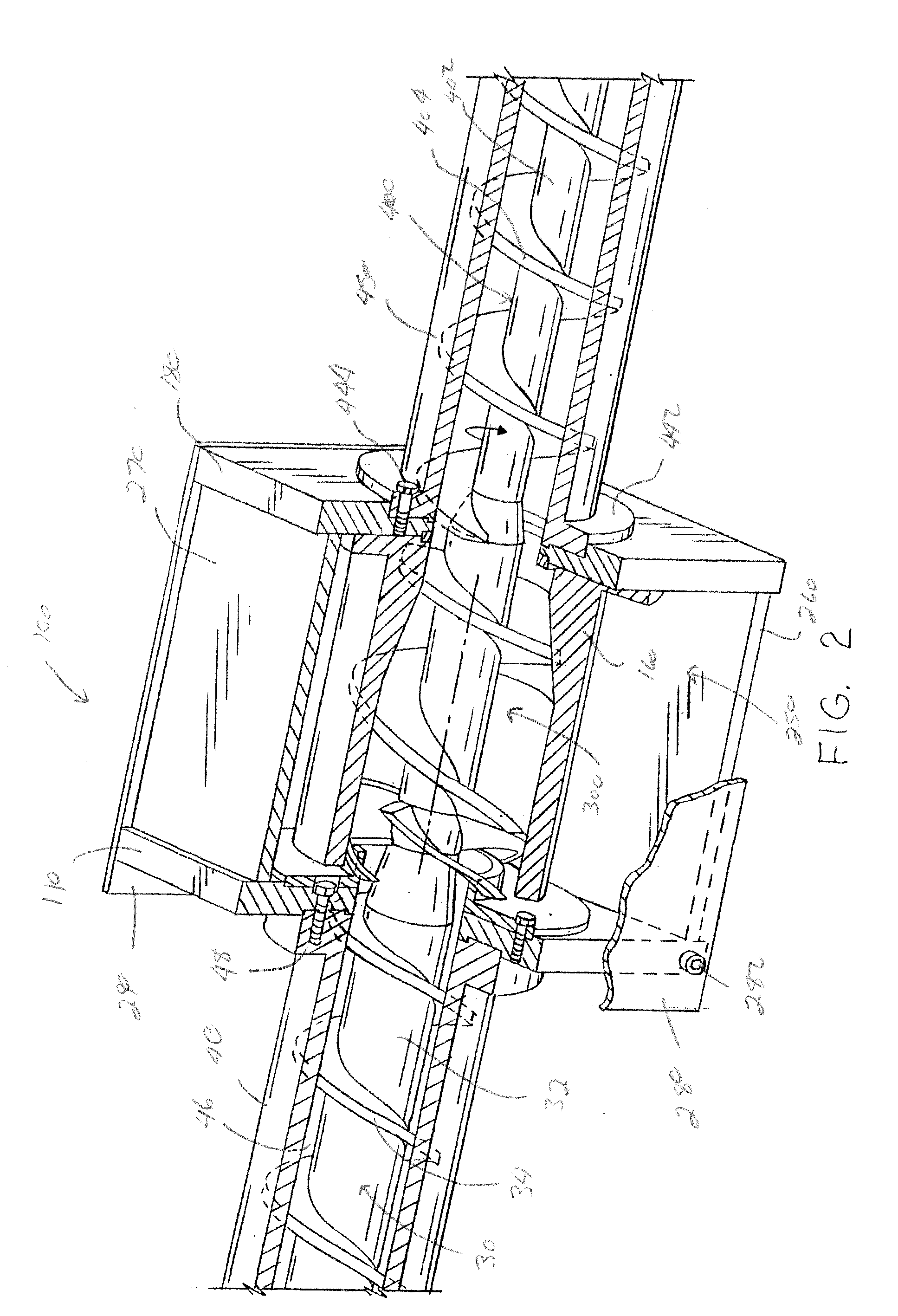
[0010]In yet another and / or alternative non-limiting aspect of the invention, the improved extruder arrangement of the present invention includes a vent block that has a vent cavity and / or screw element that are designed to cause a pressure drop as material is fed into the vent cavity; however, this is not required. The pressure drop is designed to limit or prevent material from flowing into the one or more gaps or openings in the vent cavity that are used to pull a vacuum on the vent cavity. The creation of a pressure drop can be achieved in one or more ways, such as, but not limited to, 1) creating a portion of the vent cavity having a larger cross-sectional size to the cross-sectional size of the opening in the inner feed ring, 2) reducing the root portion of the screw element as compared to the root of the auger or screw feeding material into the vent block, and / or 3) increasing the pitch of the one or more flights on the screw element as compared to the flight pitch of the auger or screw feeding material into the vent block.
[0013]It is one non-limiting object of the present invention to provide an extruder arrangement that can remove gas from material that is being fed through the extruder.
[0015]It is still another and / or alternative non-limiting object of the present invention to provide an extruder arrangement that includes a vent block having an inner feed ring and an outer ring and which rings are used to enable gas to be removed from a vent cavity while material is fed through the vent cavity and to inhibit or prevent material from moving into and / or clogging one or more gaps or openings that are used to remove gas from the vent cavity.
[0016]It is yet another and / or alternative non-limiting object of the present invention to provide an extruder arrangement that includes a vent block that includes a screw element having one or more fingers that are used to inhibit or prevent material from moving into and / or clogging one or more gaps or openings that are used to remove gas from the vent cavity.

Problems solved by technology

The entrapped air and / or other types of gasses can interfere with the proper processing of the materials in the extruder.
As such, standard extruder arrangements that include a venting system cannot be used with highly viscous materials or non-true liquid materials.

Method used


Image

  • Apparatus and process for de-airing material in an extruder
  • Apparatus and process for de-airing material in an extruder
  • Apparatus and process for de-airing material in an extruder

Examples


Embodiment Construction

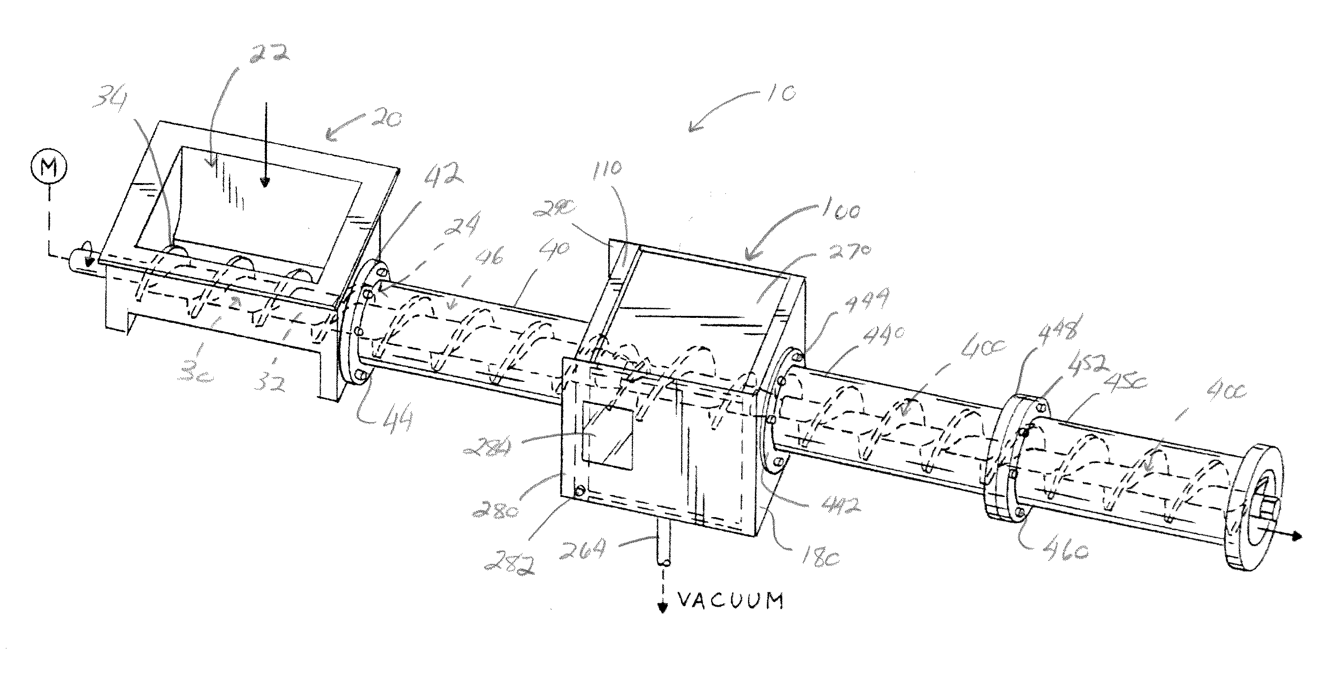
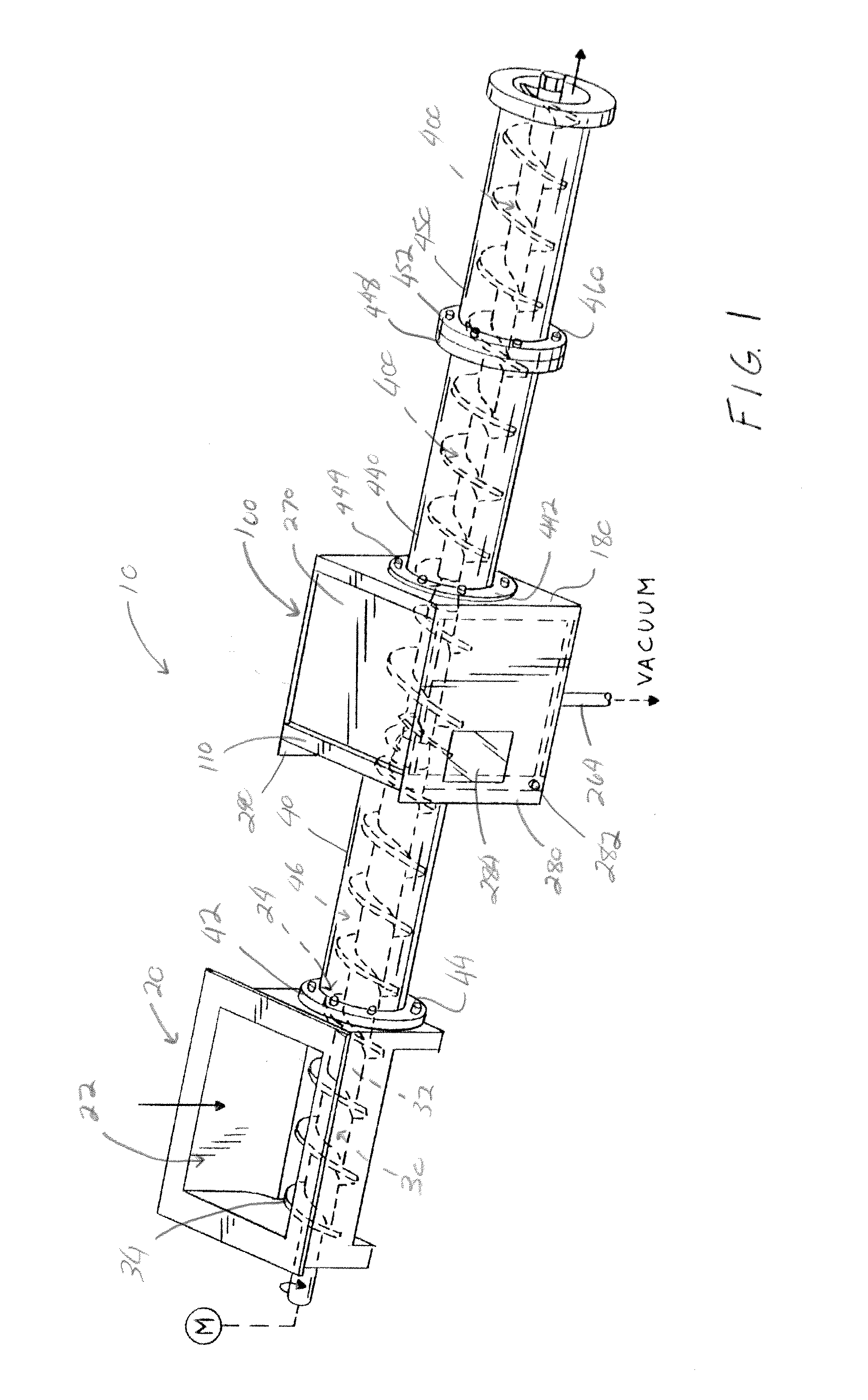
[0025]Referring now to the drawings wherein the showings are for the purpose of illustrating one non-limiting embodiment of the invention only and not for the purpose of limiting same, FIGS. 1-4 illustrate one non-limiting embodiment of the extruder arrangement in accordance with the present invention. The extruder arrangement 10 is designed to remove one or more gasses (e.g., air, nitrogen, water vapor, volatiles, etc.) from the material being feed through the extruder arrangement. The one or more gasses can create gas bubbles in the final product and / or interfere with the proper extrusion of the final product, thus compromising the integrity and / or quality of the final product extruded from the extruder arrangement. The extruder arrangement 10 is particularly useful in the extrusion of highly viscous materials and / or non-true liquids (e.g., clay materials, ceramic materials, etc.) and will be described with particular reference thereto; however, it will be appreciated that materia...


PUM

PropertyMeasurementUnit
viscosityaaaaaaaaaa
sizeaaaaaaaaaa
longitudinal lengthaaaaaaaaaa

Abstract

An extruder for feeding material and for removing gas from the fed material. The extruder includes a vent block positioned between a first and second auger. The vent block including a vent cavity having a feed end and an exit end, an inner feed ring that partially extends into said vent cavity at the feed end of the vent cavity, and a screw element rotatably positioned in the vent cavity. A front portion of the outer ring is longitudinally aligned with or overlapping the front end of the inner feed ring. The outer ring forms at least one gap or opening at or adjacent the feed end of the vent cavity to enable gas to flow out of the vent cavity as material is moved though the vent cavity from the feed end to the exit end by the screw element.

Description

[0001]The present invention claims priority on U.S. Provisional Application Ser. No. 61 / 418,631 filed Dec. 1, 2010, which is fully incorporated herein by reference.[0002]The present invention is a device used to remove gas and / or moisture from a material being process by an extruder.BACKGROUND OF THE INVENTION[0003]Many types of materials that are processed in an extruder can include entrapped air and / or other types of gasses. The entrapped air and / or other types of gasses can interfere with the proper processing of the materials in the extruder. Various arrangements have been developed to remove air and / or other types of gasses during the processing of materials in the extruder. Non-limiting examples of such arrangements are disclosed in U.S. Pat. Nos. 2,833,750; 2,944,047; 3,040,005; 3,156,009; 3,177,272; 3,799,234; 3,870,284; 3,985,348; 4,065,532; 4,100,244; 4,127,635; and 4,155,655, all of which are incorporated herein by reference.[0004]Many prior art extruder systems that incl...

Claims


Application Information

Patent Timeline
Patent Type & Authority Applications(United States)
IPC IPC(8): B29C47/76B29C48/38B29C48/395B29C48/52B29C48/76
CPCB29C47/0009B29C47/50B29C47/763B29C47/6018B29C47/385B29C47/6012B29C47/767B29C48/763B29C48/38B29C48/52B29C48/53B29C48/397B29C48/767B29C48/03B29B7/845B29B7/86
Inventor HOUK, KURT G.
Owner THE BONNOT
Learn More