Walking training apparatus

a training apparatus and walking technology, applied in walking aids, physical therapy, chiropractic devices, etc., can solve the problems of uncomfortable feeling and unsecure support of walking trainees, and achieve the effects of minimizing fatigue of walking trainees, eliminating load, and eliminating load

Active Publication Date: 2014-12-25
P&S MECHANICS
View PDF12 Cites 17 Cited by
  • Summary
  • Abstract
  • Description
  • Claims
  • Application Information

AI Technical Summary

Benefits of technology

[0021]A walking training apparatus in accordance with an exemplary embodiment includes a joint motion robot supporting unit supporting the joint motion robot and as well as eliminating a weight load of the joint motion robot to eliminate the load occurred by own weight of the joint motion robot, and thus the own weight of the joint motion robot is not shifted to the walking trainee during rehabilitation training, thereby minimizing fatigue of walking trainee during rehabilitation training and maximizing an efficiency of rehabilitation training.
[0022]In addition, a joint motion robot supporting unit of an exemplary embodiment includes a horizontal movable unit and a vertical movable unit which may adjust a position of the joint motion robot to be able precisely adjust a position of the joint motion robot supporting unit in accordance with a state of the walking trainee and a training purpose, thereby providing secure walking training for the walking trainee.

Problems solved by technology

In addition, a body of the walking trainee moves up-and-down in accordance with a walking of the walking trainee during rehabilitation training but, in the typical supporting device for the walking assist device, a distance between the frame and the walking trainee of is determined by a parallelogram structure and the walking assist device moves back and forth in accordance with a height change, and thus the walking trainee is not securely supported and feels uncomfortable during rehabilitation training.

Method used


Image

  • Walking training apparatus
  • Walking training apparatus
  • Walking training apparatus

Examples


Embodiment Construction

[0027]Hereinafter, detailed descriptions of specific embodiments described below provide various descriptions of the specific embodiments of the present invention. The present invention may, however, be embodied in different forms and should not be construed as limited to the embodiments set forth herein. A detailed description is described with reference to the accompanying drawings in which the same reference number represents the same or functionally similar elements.

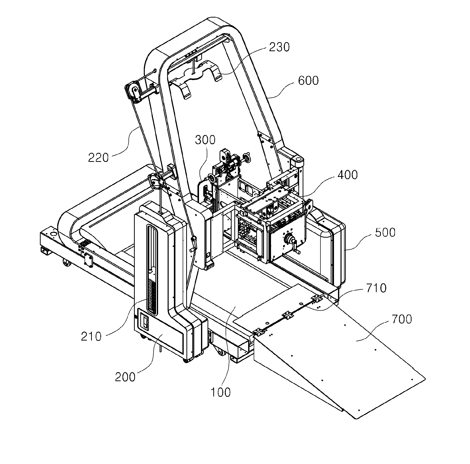
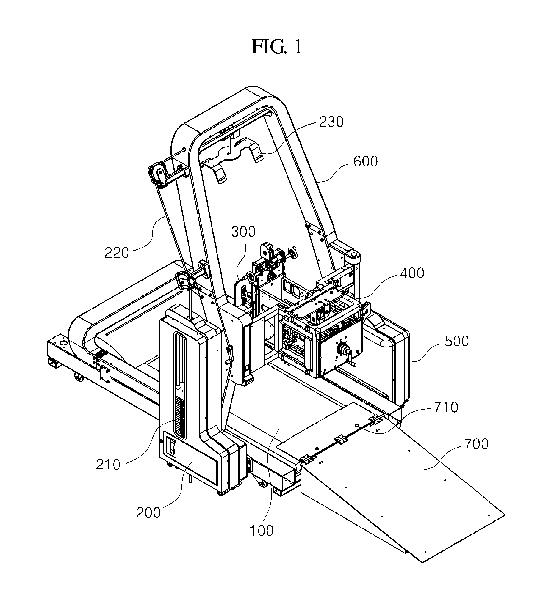
[0028]FIG. 1 is a cross-sectional view illustrating a walking training apparatus in accordance with an exemplary embodiment, and the walking training apparatus in accordance with an exemplary embodiment includes a treadmill 100; a counterload unit 200 for a walking trainee; a joint motion robot 300; a joint motion robot supporting unit 400; a control unit (not shown); a supporting frame 600 supporting the treadmill 100, the counterload unit 200 for a walking trainee, the joint motion robot 300, the joint motion robot...


PUM


Abstract

The present invention relates to a walking training apparatus. The walking training apparatus includes: a treadmill providing a bottom surface to allow a user who is training to walk to do so in a stationary position; a user counterweight unit including a counterweight, a wire, and a harness jacket, wherein the user counterweight unit lifts the user's body upward in order to reduce the load from the user's weight; a joint motion robot worn on one lower leg of the walker, wherein the joint motion robot is constituted by a hip-joint motion part, a knee-joint motion part, and an ankle-joint motion part; a joint motion robot support part supporting and coupled to the joint motion robot to reduce the load of the weight of the joint motion robot, wherein the joint motion robot support includes a horizontal movable part and a vertical movable part for moving the joint motion robot; and a control unit linked with at least one of the treadmill, the user counterweight unit, the joint motion robot, and the joint motion robot support in order to generate a customized control signal according to the user and to transmit the signal.

Description

TECHNICAL FIELD[0001]The present disclosure relates to a walking training apparatus, and more particularly, to a walking training apparatus capable of eliminating a weight load of a joint motion robot and including a horizontal movable unit and a vertical movable unit to transfer the joint motion robot, in order to support and control the joint motion robot according to a state of a walking trainee or purposes of rehabilitation therapy and the like.BACKGROUND ART[0002]In general, a walking assist device is an instrument to assist walking of a walking trainee with walking handicap, the walking assist device which is used to help training or daily life of the walking trainee who wears it and be installed on a treadmill for the walking trainee to perform repeat walking for rehabilitation training for a walking trainee.[0003]In the latter case, since the walking trainee performs rehabilitation training on the treadmill, a walking assist device supporting unit is necessary to install and...

Claims


Application Information

Patent Timeline
Patent Type & Authority Applications(United States)
IPC IPC(8): A63B23/04A61H3/00A63B22/02
CPCA63B23/0405A61H3/008A63B22/0235A61H1/024A61H1/0244A61H1/0262A61H1/0266A61H2201/1652A61H2201/1676A61H2201/5069A61H2201/5079A61H2203/0406A61H2203/0487A63B21/00181A63B21/154A63B22/02A63B23/04A63B2024/0093A63B21/0628A61H3/00
Inventor PARK, KWANG HUNLEE, DONG CHANLEE, KI HONGLEE, KYUNG HWAN
Owner P&S MECHANICS
Why Eureka
Try Eureka