System and method for automatic location assignment of wheels equipped with pressure sensors

Inactive Publication Date: 2014-12-25
DELPHI TECH INC
View PDF2 Cites 8 Cited by
  • Summary
  • Abstract
  • Description
  • Claims
  • Application Information

AI Technical Summary

Benefits of technology

The patent describes a system and method for monitoring the pressure of tires on a vehicle to determine which wheel they are located on. This is achieved by equipping each wheel with a pressure sensor that can detect pressure variations caused by low tire pressure or damage to the tire. These pressure variations are then used to determine the wheel location, which can help to improve tire safety and performance. The system includes a controller and processor that analyzes the pressure data from each sensor to make this determination. Overall, the technical effect of the patent is to provide a reliable and effective way to identify which wheel is experiencing low tire pressure or damage, and to alert the driver or other safety mechanisms in a timely manner.

Problems solved by technology

Various ways for a system to automatically learn or self-train the wheel locations have been proposed, some of which require the undesirable addition of costly hardware.

Method used


Image

  • System and method for automatic location assignment of wheels equipped with pressure sensors
  • System and method for automatic location assignment of wheels equipped with pressure sensors
  • System and method for automatic location assignment of wheels equipped with pressure sensors

Examples


Embodiment Construction

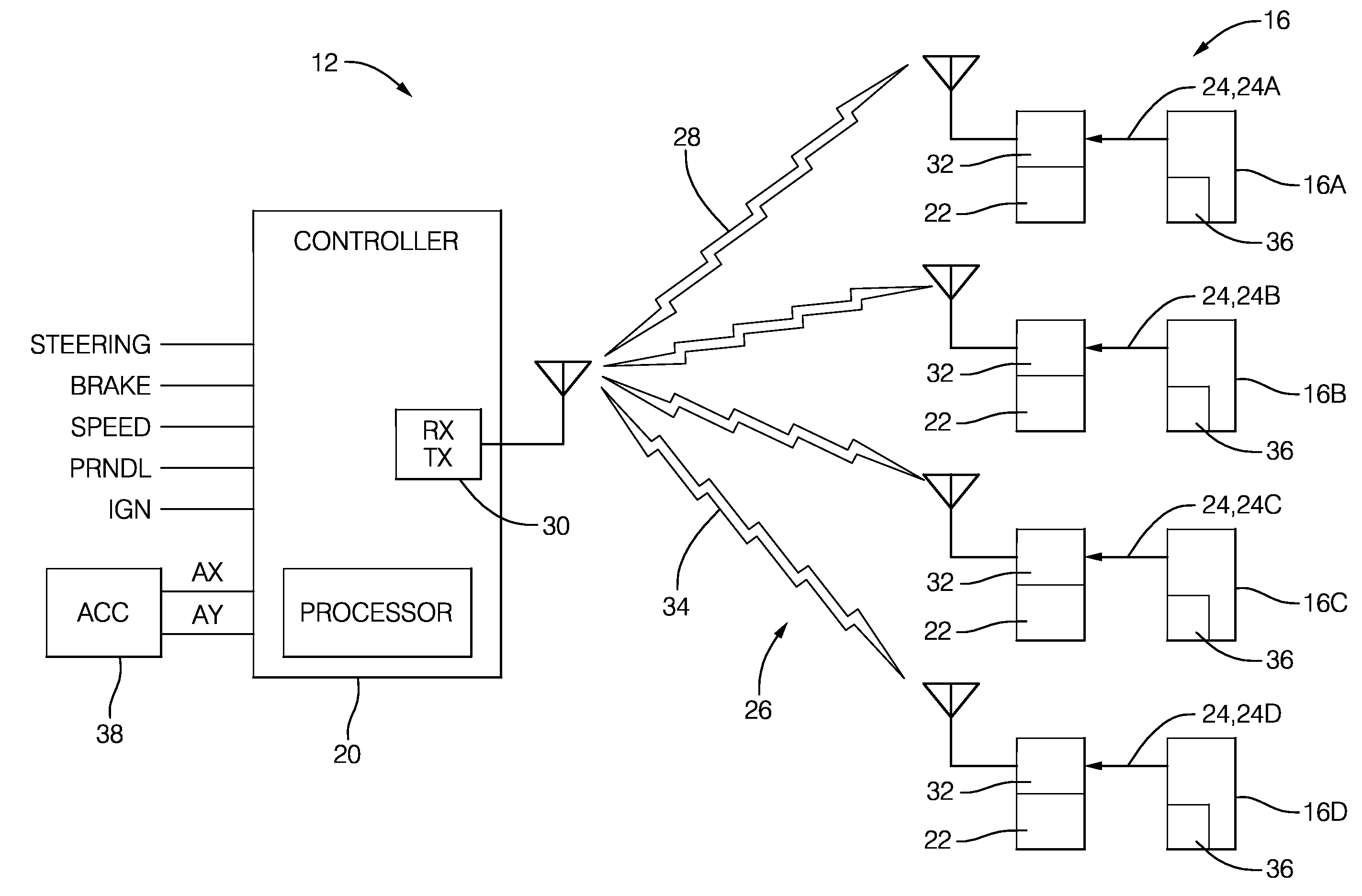
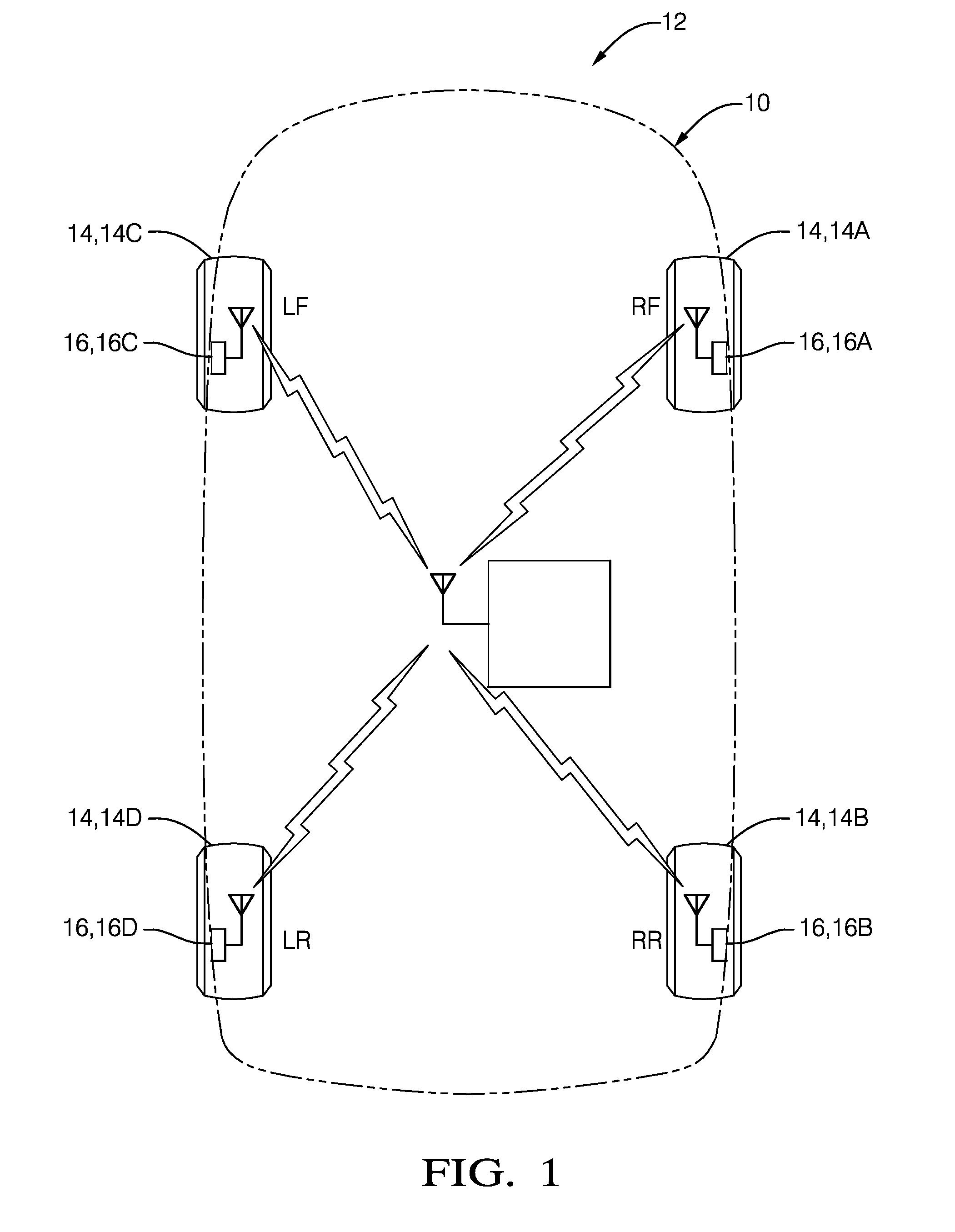
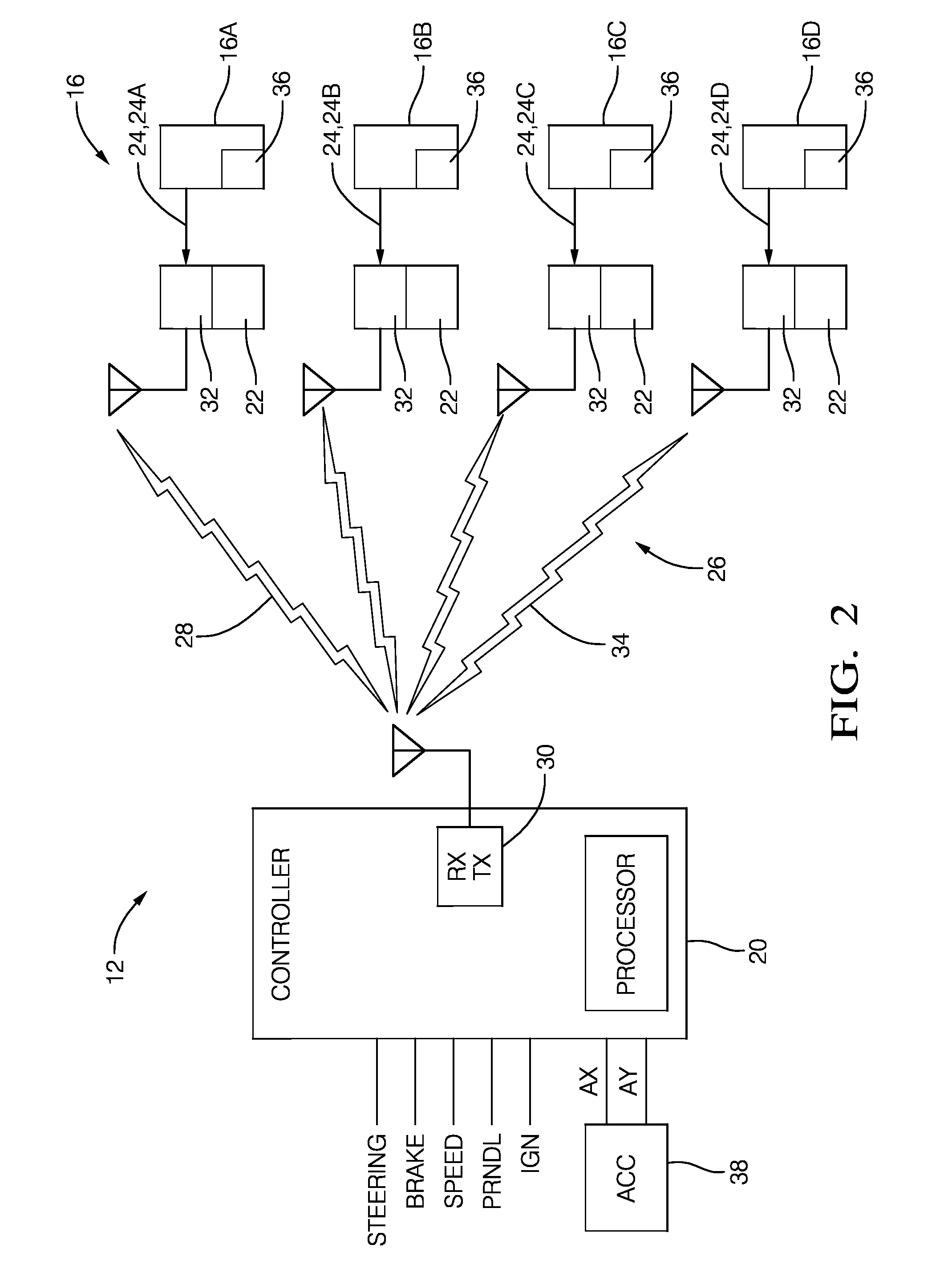
[0016]Described herein is a tire pressure monitor system and method that uses variation or fluctuations of tire pressure to determine the location (e.g.—right front (RF), the right rear (RR), the left-front (LF), and the left-rear (LR)) of a wheel on a vehicle. In general, suitable variations of tire pressure are transient in nature, typically caused by the vehicle turning or the vehicle driving over some irregularity in the roadway. The variations are analyzed, and a comparison of these pressure variations from one wheel to the other is used to determine wheel location. As such, the wheel location can be determined by the system without manual programming or other intervention by a service technician or owner of the vehicle, i.e. the system has an automatic wheel location assignment feature. The system and method overcome a long standing problem of automating the learning of the wheel location without adding undesirable expense to the vehicle, and avoids potential human error since...


PUM


Abstract

A method of operating a tire pressure monitor system on a vehicle to determine a wheel location of wheels equipped with pressure sensors. The method includes equipping a plurality of wheels with a pressure sensor, determining a plurality of pressure values from each pressure sensor, detecting a variation of the pressure values from a plurality of pressure sensors, and determining a wheel location based on a comparison of the variations of the pressure values. Variations useful for determining wheel location may include running over an object such as a rumble strip or pot-hole on the roadway, or the vehicle executing a turn.

Description

TECHNICAL FIELD OF INVENTION[0001]This disclosure generally relates to tire pressure monitor systems, and more particularly relates to determining wheel locations of wheels equipped with pressure sensors based on a comparison of variations of the pressure values that occur while the vehicle is being operated.BACKGROUND OF INVENTION[0002]Some vehicles are equipped with tire pressure monitor systems. These systems typically indicate tire pressure for a wheel at a particular wheel position or wheel location. For example, the system individually indicates the tire pressure for the right front (RF), the right rear (RR), the left-front (LF), and the left-rear (LR) wheel locations. Some systems require action on the part of a service technician or vehicle owner to re-program the wheel locations if the locations of the wheels are changed. Various ways for a system to automatically learn or self-train the wheel locations have been proposed, some of which require the undesirable addition of c...

Claims


Application Information

Patent Timeline
IPC IPC(8): B60C23/04
CPCB60C23/04B60C23/0416B60C23/0477
Inventor HAWES, KEVIN J.RUPPEL, CHRISTOPHER D.OMAN, TODD P.
Owner DELPHI TECH INC
Why Eureka
Try Eureka