Method for checking cooling holes of a gas turbine blade

a gas turbine blade and cooling hole technology, applied in the direction of mechanical equipment, machines/engines, instruments, etc., can solve the problems of not meeting all checking requirements, the accuracy of measuring methods is low, and the dimensions of these blades will change, so as to improve the efficiency of checking, improve the efficiency of measurement and comparison, and improve the effect of checking efficiency

Inactive Publication Date: 2015-01-01
SIEMENS AG
View PDF8 Cites 14 Cited by
  • Summary
  • Abstract
  • Description
  • Claims
  • Application Information

AI Technical Summary

Benefits of technology

[0009]According to another aspect of the present invention, steps 1 to 4 are performed on multiple cooling holes at the same time. Obtaining and scanning models of multiple cooling holes at the same time allows the efficiency of checking to be further improved.
[0010]According to another aspect of the present invention, the data about the standard model in the method is obtained by performing steps 1 to 4 in sequence. By making a comparison with data about the standard model obtained by the same method, the efficiency of measurement and the accuracy of comparison can be improved.
[0011]According to another aspect of the present invention, before step 1 the method further comprises: step 11: covering the inner wall of the cooling hole with a layer of mold-release coating. The mold-release coating can facilitate the release of the liquid plastic material from the mold after curing.

Problems solved by technology

However, because they operate for long periods under heavy loads in temperature conditions of several hundred or even over a thousand degrees, changes will occur in the dimensions of these blades due to wear.
Since the cooling holes are of small dimensions, have a complex structure in practice and continuously varying angles of inclination, while the measuring probe 2 is ductile, these measuring methods have a low level of accuracy, and typically cannot satisfy all checking requirements.
However, such a method is capable of checking the surface condition of the gas turbine blade only, and not the cooling holes of the gas turbine blade.
Although this method gives improved accuracy of measurement, and allows cooling holes of gas turbine blades to be measured, it involves complex equipment, is time-consuming and expensive, and is not suitable for checking large quantities of components in the factory.

Method used


Image

  • Method for checking cooling holes of a gas turbine blade
  • Method for checking cooling holes of a gas turbine blade
  • Method for checking cooling holes of a gas turbine blade

Examples


Embodiment Construction

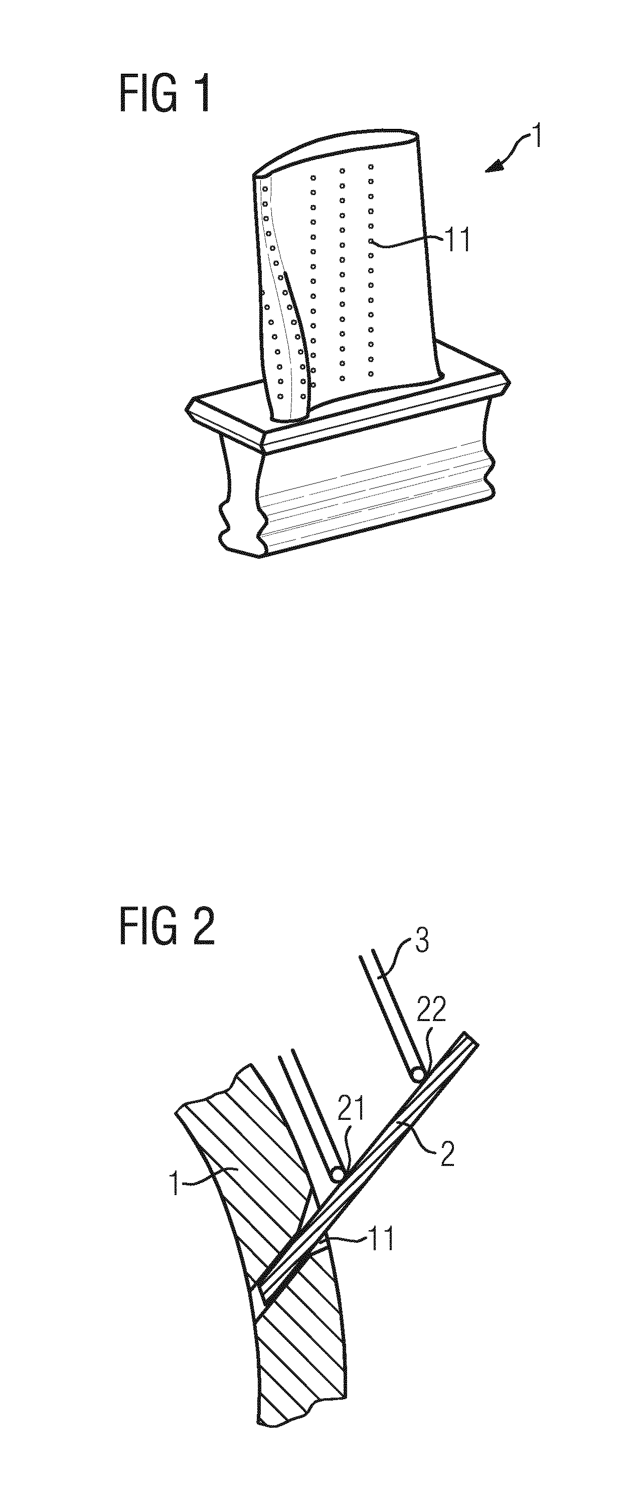
[0019]In order that the technical features, object and effects of the present invention may be understood more clearly, particular embodiments of the present invention will now be described with reference to the accompanying drawings, in which identical labels and require numbers indicate identical parts or parts that are similar in structure but identical in function.

[0020]In order that the drawings may appear simple and clear, only those parts which are relevant to the present invention are shown schematically therein; these do not represent the actual structure thereof as a product. Furthermore, in order that the drawings may appear simple and clear for ease of understanding, if there are parts with the same structure or function in certain drawings, only one of these is drawn schematically or marked.

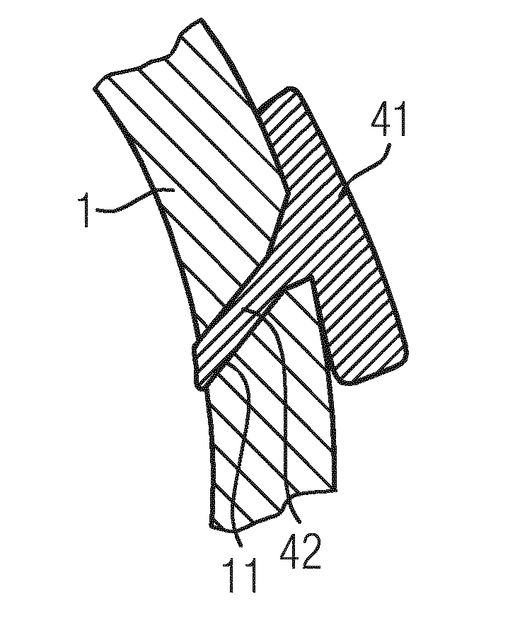
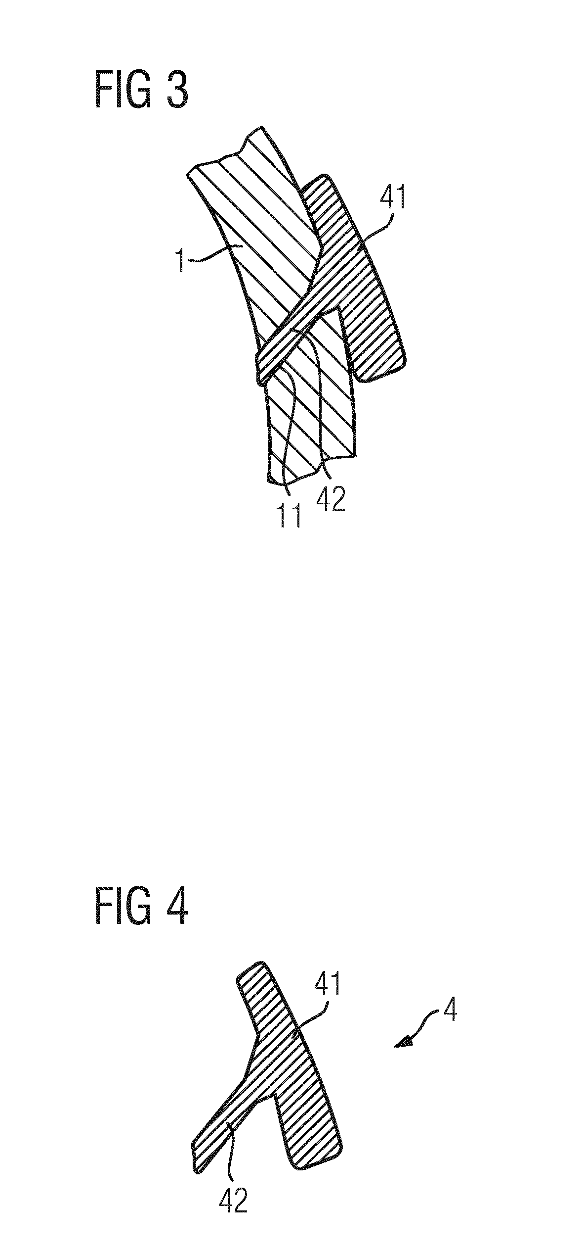
[0021]FIG. 3 uses a sectional view to show the method of the present invention for checking cooling holes of a gas turbine blade. Those skilled in the art will understand that the me...


PUM


Abstract

A method for checking cooling holes of a gas turbine blade, including in sequence: step 1: injecting a liquid plastic material into a cooling hole of a gas turbine blade; step 2: stopping the flow of the liquid plastic material, and curing the liquid plastic material to form a model; step 3: separating the model from the gas turbine blade; step 4: scanning the model. By scanning the model, the cooling holes of the gas turbine blade can be checked, so as to obtain more data about the position, dimensions and shape thereof, while improving the accuracy and efficiency of measurement.

Description

CROSS-REFERENCE TO RELATED APPLICATIONS[0001]The present application is a 35 U.S.C. §§371 national phase conversion of PCT / EP2013 / 053645, filed Feb. 25, 2013, which claims priority of Chinese Patent Application No. 201210050578.9, filed Feb. 29, 2012, the contents of which are incorporated by reference herein. The PCT International Application was published in the English language.TECHNICAL FIELD[0002]The present invention relates to a method for checking cooling holes of a gas turbine blade.BACKGROUND ART[0003]Stationary blades or rotor blades of gas turbines often operate in conditions of high temperature and pressure, and the various dimensions thereof are crucial for a gas turbine to operate well. However, because they operate for long periods under heavy loads in temperature conditions of several hundred or even over a thousand degrees, changes will occur in the dimensions of these blades due to wear. This is particularly true in the case of cooling holes 11 of the exemplary ga...

Claims


Application Information

Patent Timeline
Patent Type & Authority Applications(United States)
IPC IPC(8): F01D5/18G01B11/26G01B11/24G01B11/14F01D5/14
CPCF01D5/147F01D5/186F05D2300/43G01B11/14G01B11/24G01B11/26F01D5/005
Inventor JIANG, TAOLI, HONG TAONEUENHAHN, THOMAS
Owner SIEMENS AG
Why Eureka
Try Eureka