Fusible alloy plug in flow control device

a flow control device and alloy plug technology, applied in drinking water installation, borehole/well accessories, insulation, etc., can solve the problems of individual vendor applications, mechanical shifting, and dependability of actuation, and achieve the effect of restricting hydraulic flow

Active Publication Date: 2015-01-01
CONOCOPHILLIPS CO +1
View PDF1 Cites 7 Cited by
  • Summary
  • Abstract
  • Description
  • Claims
  • Application Information

AI Technical Summary

Benefits of technology

[0008]The disclosure relates to an apparatus for isolating flow within a wellbore. The system components include a flow control device, usually used in combination with an e

Problems solved by technology

Mechanical and hydraulic systems have been implemented in the past, however, the major disadvantages to these type of systems include complexity, mov

Method used


Image

  • Fusible alloy plug in flow control device
  • Fusible alloy plug in flow control device
  • Fusible alloy plug in flow control device

Examples


Embodiment Construction

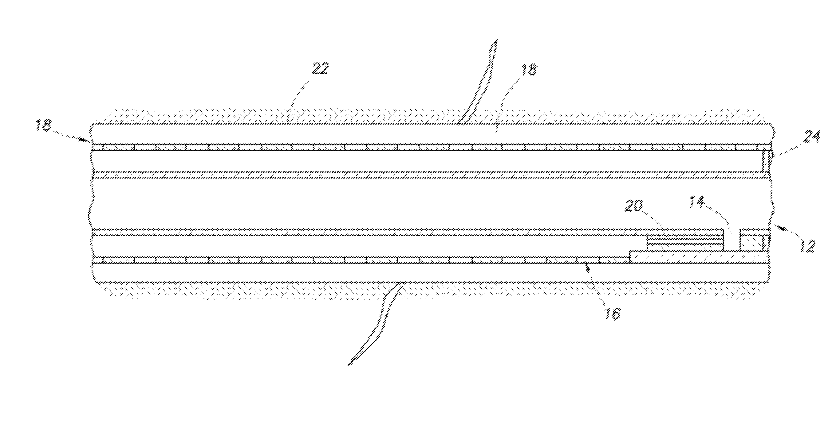
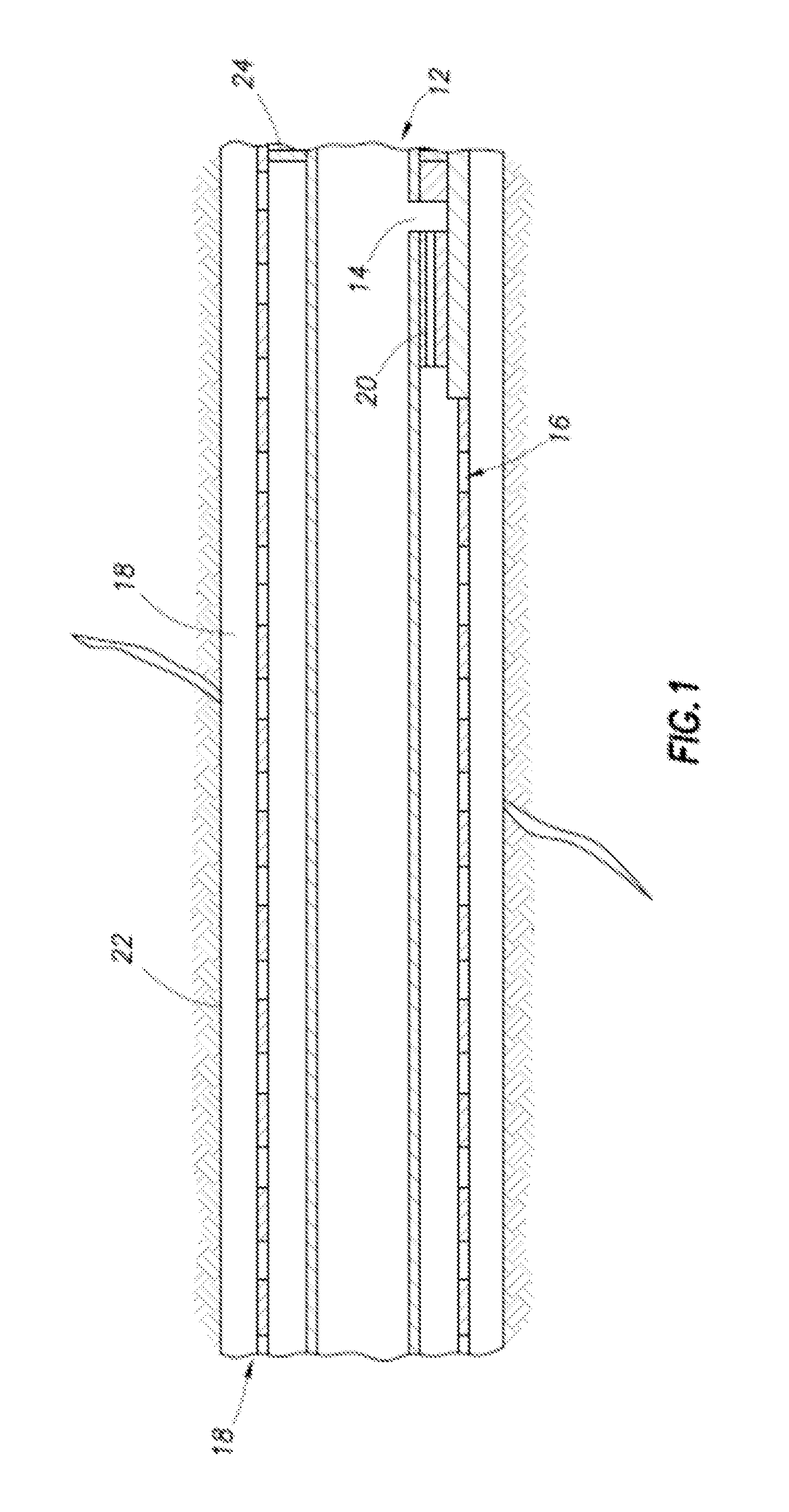
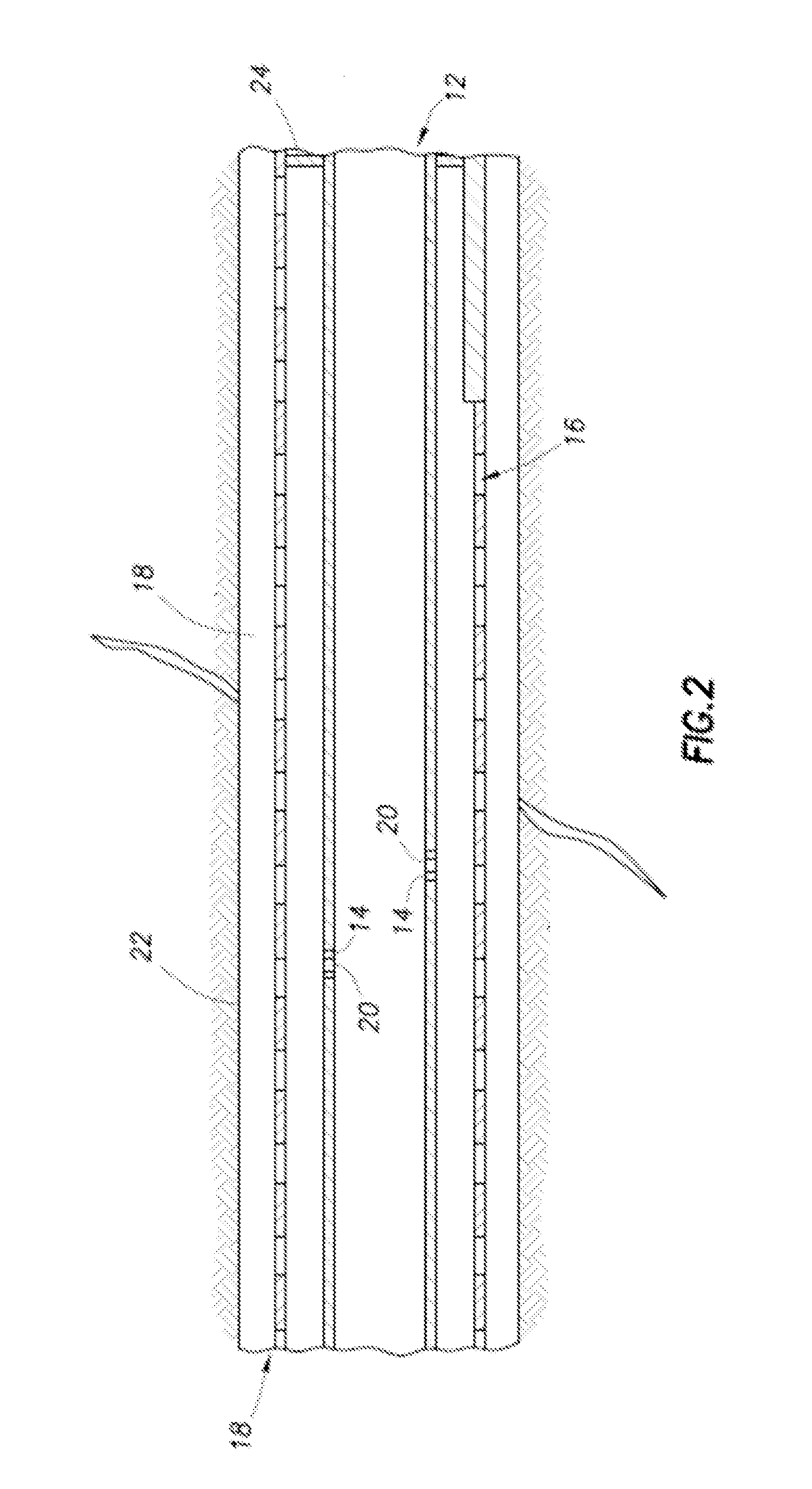
[0044]The present disclosure describes a novel device for control flow in an oil reservior and methods of use thereof. Specifically, temporary fusible alloy plugs are used in flow control devices. The plug can be passively removed upon contact with high temperatures.

[0045]The disclosure includes one or more of the following embodiments, in any combination:

[0046]An apparatus for isolating flow within a wellbore comprising a flow control device with an exclusion media, wherein the flow control device includes at least one aperture formed therein, wherein the aperture restricts hydraulic flow, wherein the exclusion media limits the flow of formation materials; and a temporary fusible alloy plug securely installed into said at least one aperture, wherein the temporary fusible alloy plug can be passively removed upon thermal circulation or injection operations.

[0047]An apparatus for isolating flow within a wellbore comprising a flow control device, wherein the flow control device include...


PUM


Abstract

A “passive” apparatus and method for isolating flow within a thermal wellbore wherein inflow apertures are plugged with a temporary fusible alloy plug that can be selectively removed by increasing the wellbore temperature.

Description

PRIOR RELATED APPLICATIONS[0001]This application claims priority to U.S. application Ser. No. 61 / 841,645, filed Jul. 1, 2013, and is expressly incorporated by reference herein in its entirety for all purposes.FEDERALLY SPONSORED RESEARCH STATEMENT[0002]Not applicable.FIELD OF THE DISCLOSURE[0003]This invention relates to an apparatus and method for isolating flow within a thermal wellbore.BACKGROUND OF THE DISCLOSURE[0004]Many different tasks may be performed in a wellbore. For example, perforating guns may be shot to create perforations in a target formation in order to produce well fluids to the surface; different zones in a wellbore may be sealed with packers; plugs may be set at desired depths to isolate portions of a wellbore; a casing patch may be activated to patch openings in a casing or other type of liner; or sand screens may be installed to control production of sand. In addition to completion equipment, other tools for use in wellbores may include drilling equipment, log...

Claims


Application Information

Patent Timeline
IPC IPC(8): E21B43/08E21B34/06
CPCE21B43/08E21B34/063E21B43/2406E21B36/006E21B43/10
Inventor MADELL, GARRETSTALDER, JOHN LOWELLSTEVENSON, JESSE
Owner CONOCOPHILLIPS CO
Why Eureka
Try Eureka