

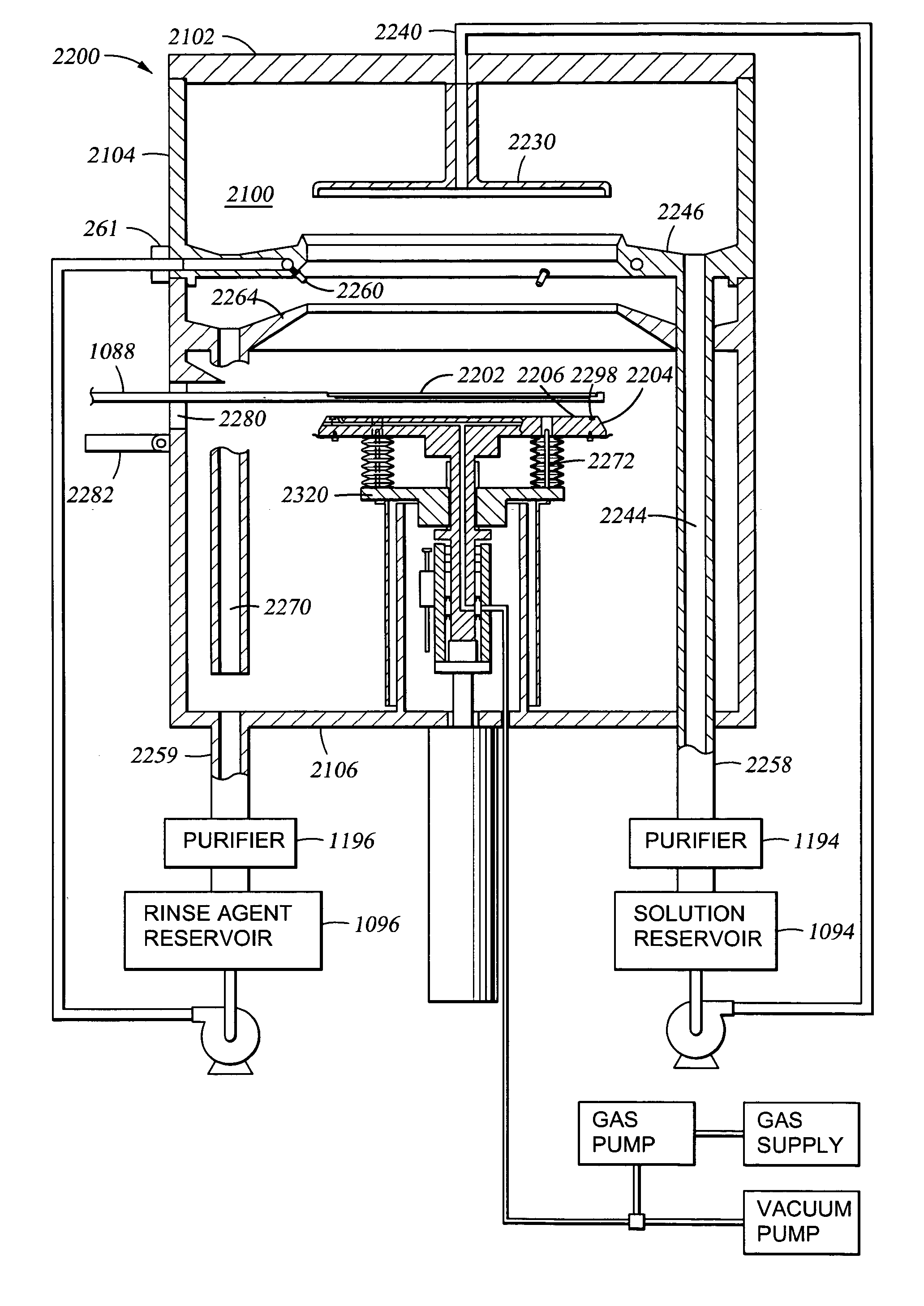
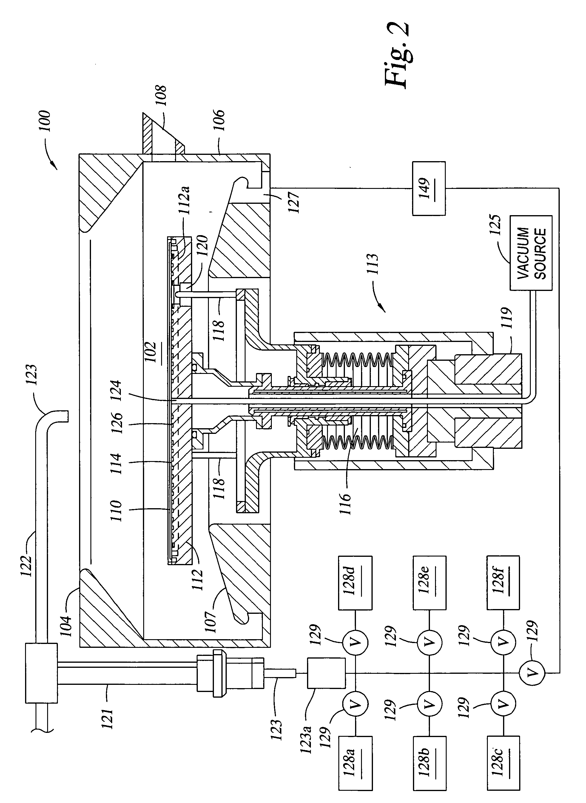
Electroless deposition apparatus
a technology of deposition apparatus and electrodes, which is applied in the direction of liquid/solution decomposition chemical coating, manufacturing tools, coatings, etc., can solve the problems of compromising the ability to deposit conformal seed layers, affecting the formation of sub-micron structures, and a great amount of ongoing effort aimed at substantially void-free structures
- Summary
- Abstract
- Description
- Claims
- Application Information
AI Technical Summary
Benefits of technology
Problems solved by technology
Method used
Image

Examples
examples
[0134] Various trials were conducted in depositing a catalytic layer and a conductive material layer. Some of the examples are set forth below.
example a
[0135] A 700 Å PVD copper seed layer was deposited over substrate structures having 0.2 micron features having an aspect ratio of about 5 to about 1. A catalytic layer comprising tin and palladium was deposited by electroless deposition over the PVD copper seed layer at a reaction temperature of about 40° C. for a time period of 30 seconds, 60 seconds, 120 seconds, or 240 seconds. The catalytic layer was deposited utilizing an electroless deposition solution comprising 0.7 g / L of Pd, 25-30 g / L of Sn, and 30%-40% of HCl by volume. Scanning electron microscope photographs of the substrates showed that for catalytic layers deposited for a time period of 120 seconds or 240 seconds, the acidic electroless deposition solution of the catalytic layer would begin to dissolve and create holes in the PVD copper seed layer. Catalytic layers deposited for a time period of 30 seconds or 60 seconds showed good step coverage of the features without creating holes in the PVD copper seed layer.
example b
[0136] A thin PVD copper seed layer was deposited over substrate structures having 0.2 micron features having an aspect ratio of about 5 to about 1. A catalytic layer comprising tin and palladium was deposited by electroless deposition over the thin PVD copper seed layer for a time period of 30 seconds at a reaction temperature of room temperature, 40° C., 60° C., or 80° C. The catalytic layer was deposited utilizing an electroless deposition solution comprising 0.7 g / L of Pd, 25-30 g / L of Sn, and 30%-40% of HCL. Scanning electron microscope photographs of the substrates showed that for catalytic layers deposited at room temperature the catalytic layer had a very rough surface.
PUM
| Property | Measurement | Unit |
|---|---|---|
| size | aaaaa | aaaaa |
| diameter | aaaaa | aaaaa |
| diameter | aaaaa | aaaaa |
Abstract
Description
Claims
Application Information