Lifting type support stand

Inactive Publication Date: 2015-01-01
HUANG MING HUA
View PDF7 Cites 42 Cited by
  • Summary
  • Abstract
  • Description
  • Claims
  • Application Information

AI Technical Summary

Benefits of technology

[0006]The main object of the present invention is to provide a lifting type support stand, in which a moving distance of a drag rope is smaller than a moving distance of a first rope, second rope when a sheave is rotated, leading to the decrease of an extension, use length of an extension spring, the reduction of a reaction force of the extension spring, and the prevention of a hanging tool moving mechanism and display device from sudden rise or drop while being moved vertically, because the drag rope used to drag the extension spring surrounding along a rope race on the rear side of a sheave, which is disposed on the periphery of a scroll to form an approximately tapered spiral line, and further because the curvature radius of the rope race is smaller than the radius of the first slot way, second slot way, causing the perimeter of the rope race is smaller than the perimeter of a first slot way, second slot way.
[0007]Another object of the present invention is to provide a lifting type support stand, in which the distance between a drag rope and a sheave is varied with the rolling-up or releasing of the sheave, capable of decreasing an extension length of an extension spring, reducing a reaction force to form a force balancing state when the extension spring is exerted with a force to extend, and preventing sudden rise

Problems solved by technology

But, the display on the cabinet can not be operated to move vertically to adjust a viewed position, and a larger space must be provided for the hanging arm, support arm to allow the vertical position of the display device hung thereby to be adjusted.
Therefore, no matter that the cabinet, hanging arm or support arm is used to mount the display, it still be inconvenient in use and operation.
Furtherm

Method used


Image

  • Lifting type support stand
  • Lifting type support stand
  • Lifting type support stand

Examples


Example

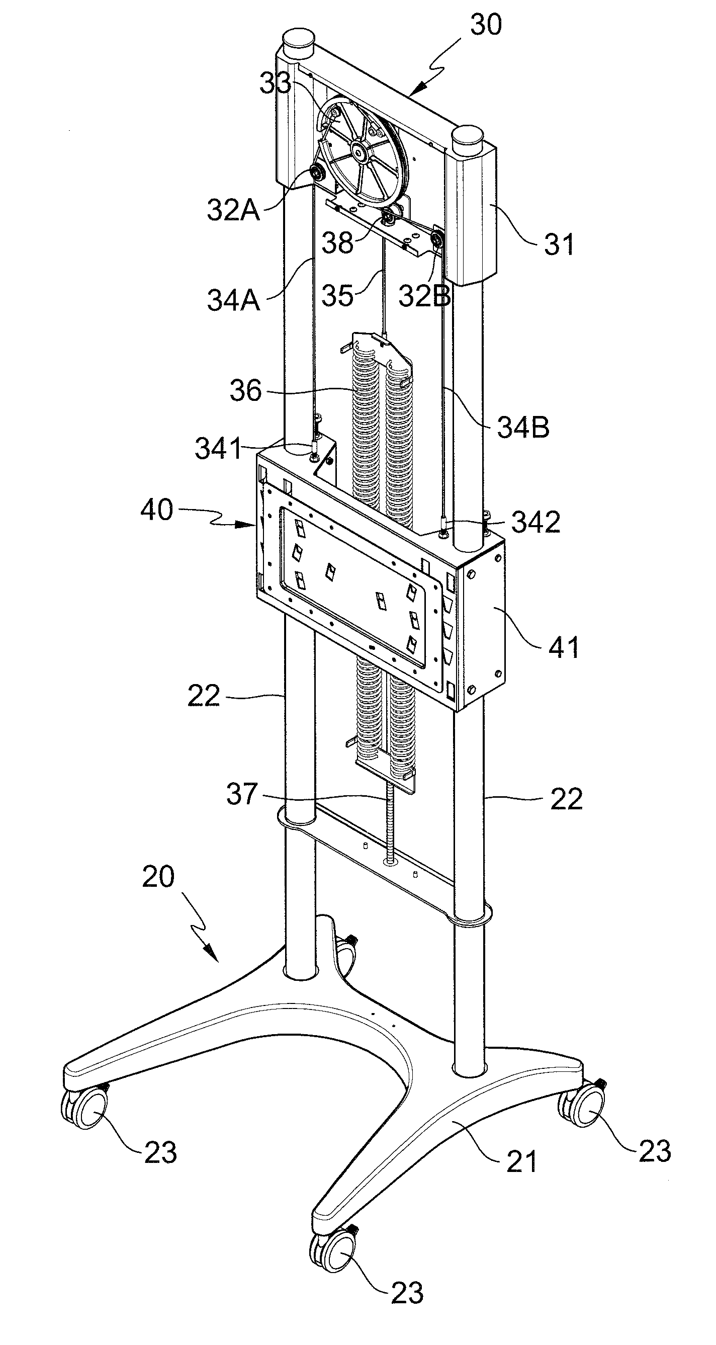
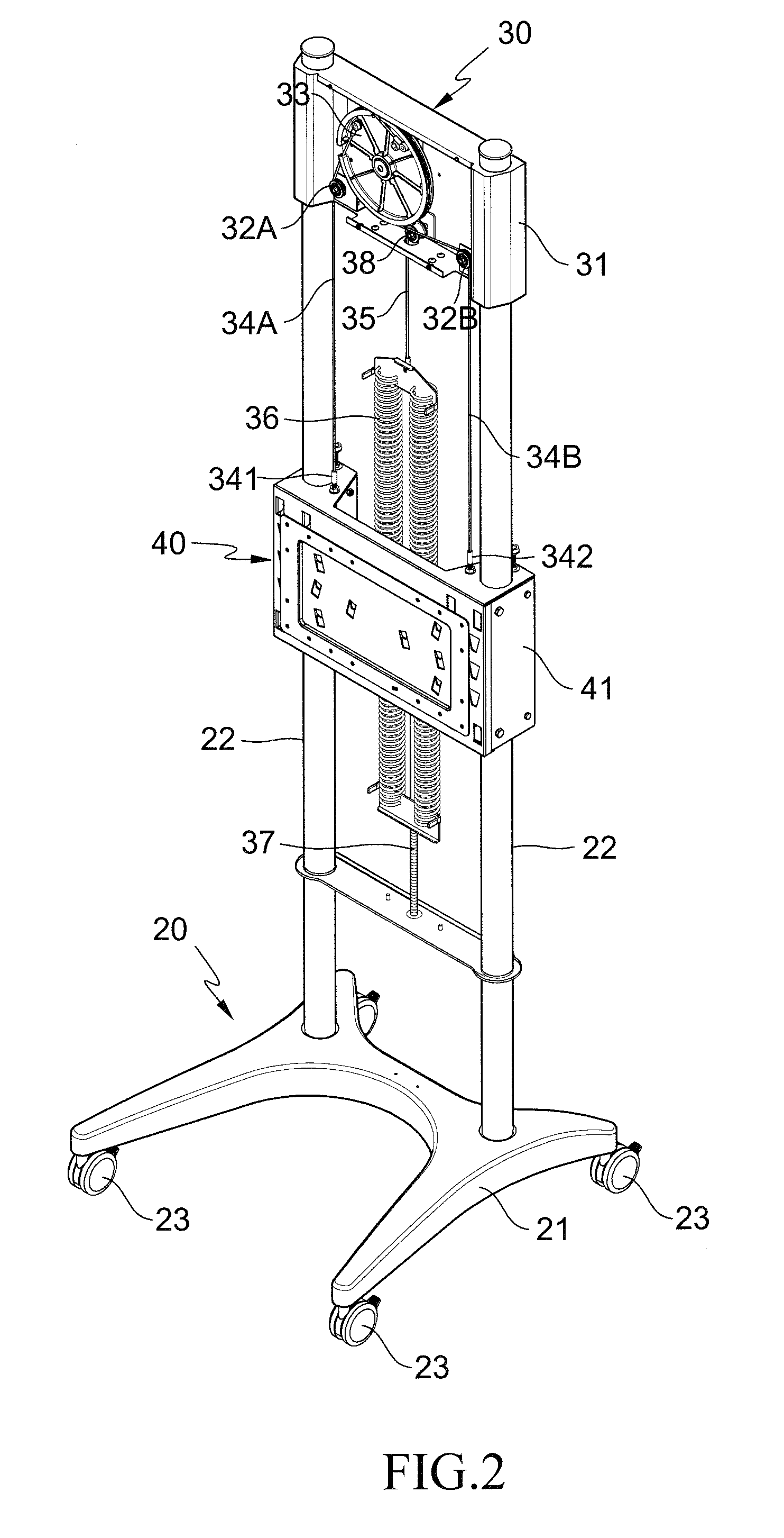
[0022]FIGS. 2 to 13 illustrate the technical means and structures applied for objects of a preferred embodiment according to the present invention.

[0023]Referring to FIG. 2, a lifting type support stand of the embodiment includes a foot stand 20, drag mechanism 30 and hanging tool moving mechanism 40.

[0024]Referring to FIG. 2 additionally besides FIG. 2, the foot stand 20 includes a base 21, and two stand columns 22 configured on the base 21, where several casters 23 may configured on the bottom of the base 21.

[0025]Referring to FIGS. 2 to 5, the drag mechanism 30 is fixed on the two stand columns 22, including a fixation seat 31, where two idle wheels 32A, 32B are configured on the lower side of the fixation seat 31, and a sheave 33 is also coupled to the fixation seat 31. A first slot way 331 and second slot way 332 are formed on the periphery of the sheave 33, and a scroll 333 is configured on one side of the sheave 33, where a height of the scroll 333 is increased with the route...


PUM


Abstract

A lifting type support stand includes a foot stand, on which a drag mechanism and hanging tool moving mechanism are mounted, where two ropes configured on a sheave is used to couple the drag mechanism to hanging tool moving mechanism. The hanging tool moving mechanism can be driven to move vertically along the foot stand when the sheave is rotated. The rear side of sheave is projected with a scroll, the periphery of which is configured with an approximately tapered spiral line rope race. The rope race is surrounded with a drag rope, two ends of which are respectively coupled to the sheave and an extension spring, a reaction force of the spring is utilized to mount the hanging tool moving mechanism and display device. Whereby, a vertical position and moving distance of a display device can be adjusted and increased by moving the drag rope on the rope race.

Description

(A) TECHNICAL FIELD OF THE INVENTION[0001]The present invention relates to a lifting type support stand, and more particularly to a lifting type support stand helpful to adjust a vertical position of a display device, increase a moving distance thereof and stop it at will steplessly.(B) DESCRIPTION OF THE PRIOR ART[0002]To provide a mount stability and convenience for a display device such as screen, whiteboard, blackboard or other planar electronic products, a cabinet (rack) is usually used to mount the display device, or a hanging arm, support arm may also be used to hang the display device, thereby achieving use convenience. But, the display on the cabinet can not be operated to move vertically to adjust a viewed position, and a larger space must be provided for the hanging arm, support arm to allow the vertical position of the display device hung thereby to be adjusted. Therefore, no matter that the cabinet, hanging arm or support arm is used to mount the display, it still be in...

Claims


Application Information

Patent Timeline
IPC IPC(8): F16M11/42F16M11/04
CPCF16M11/42F16M11/046F16M11/18F16M2200/047
Inventor HUANG, MING, HUA
Owner HUANG MING HUA
Why Eureka
Try Eureka