
Pressure-activated server cooling system

a server cooling and pressure-activated technology, applied in the field of servers, can solve the problems of insufficient passively reducing the build-up of heat and pressure within the rack, requiring impractical amounts of power, and unable to control the rack fans, so as to reduce the threat of overheating, reduce the risk of overheating, and mitigate the detrimental flow impedance

Inactive Publication Date: 2015-01-01
HEWLETT-PACKARD ENTERPRISE DEV LP
View PDF13 Cites 25 Cited by
  • Summary
  • Abstract
  • Description
  • Claims
  • Application Information

AI Technical Summary

Benefits of technology

The invention is about a system that automatically cools down servers in server racks that are overheating due to blockages in the air flow. It does this by detecting and reducing the excess pressure in the space around the server's vents, which prevents air from flowing through the server and causes it to overheat. The system is controlled and doesn't rely on temperature readings, so it can cool the server quickly and efficiently regardless of the surrounding temperature. This means that data management companies can add more components to the server racks without worrying about the air flow being blocked. Overall, the system helps prevent server overheating and ensures optimal cooling.

Problems solved by technology

Each rack fans overlaps multiple servers because using a single rack fan for each individual server requires impractical amounts of power that data management companies and their customers are unwilling to tolerate.
Although server racks are equipped with rear vents or outlets, they are insufficient to passively mitigate the build up of heat and pressure within the rack.
Although a server motherboard can control the speed of its onboard server fan, it cannot control the rack fans.
When the rack fans fail to exhaust hot air from the server rack fast enough, the build up of heat and pressure causes the servers stored inside to overheat.
Such components often partially block outlet vents and in doing so further impede the ability of the system to evacuate hot air and pressure from the server rack.
Previous attempts to solve this issue have proven inefficient, imprecise, and unattractive to customers in the data management market.
This solution presents a number of negative side effects including over-consumption of energy and markedly detrimental effects on server cooling efficiencies.
Previously attempted solutions that leave rack fans constantly running at the same speed not only waste energy by incorrectly assuming that servers are always running hot, but also pull more air through the server rack than the server itself is trying to control using its internal server fan.
In doing so, such solutions fail to precisely exhaust the hot air while leaving behind cool air that would otherwise contribute to the sort of high ΔT rating that customers in the data management industry not only find desirable but are now demanding at an increasing rate.
In such configurations, temperature-based automated cooling systems can be especially imprecise.
The result is that server A ultimately overheats while energy is wasted cooling server B when server B was already sufficiently cool in the first place.
In doing so, such solutions lower the ΔT rating of the system and ultimately make it undesirable if not unacceptable to savvy customers in the modern data management industry.
Moreover, cooling systems that depend on temperature readings can only be optimized for a single ambient temperature.
As a result, an entire room full of servers may be forced to operate in less than optimal ambient temperature conditions that are maintained as a compromise across multiple servers that each have their own optimal operating conditions.

Method used


Image

  • Pressure-activated server cooling system
  • Pressure-activated server cooling system
  • Pressure-activated server cooling system

Examples


Embodiment Construction

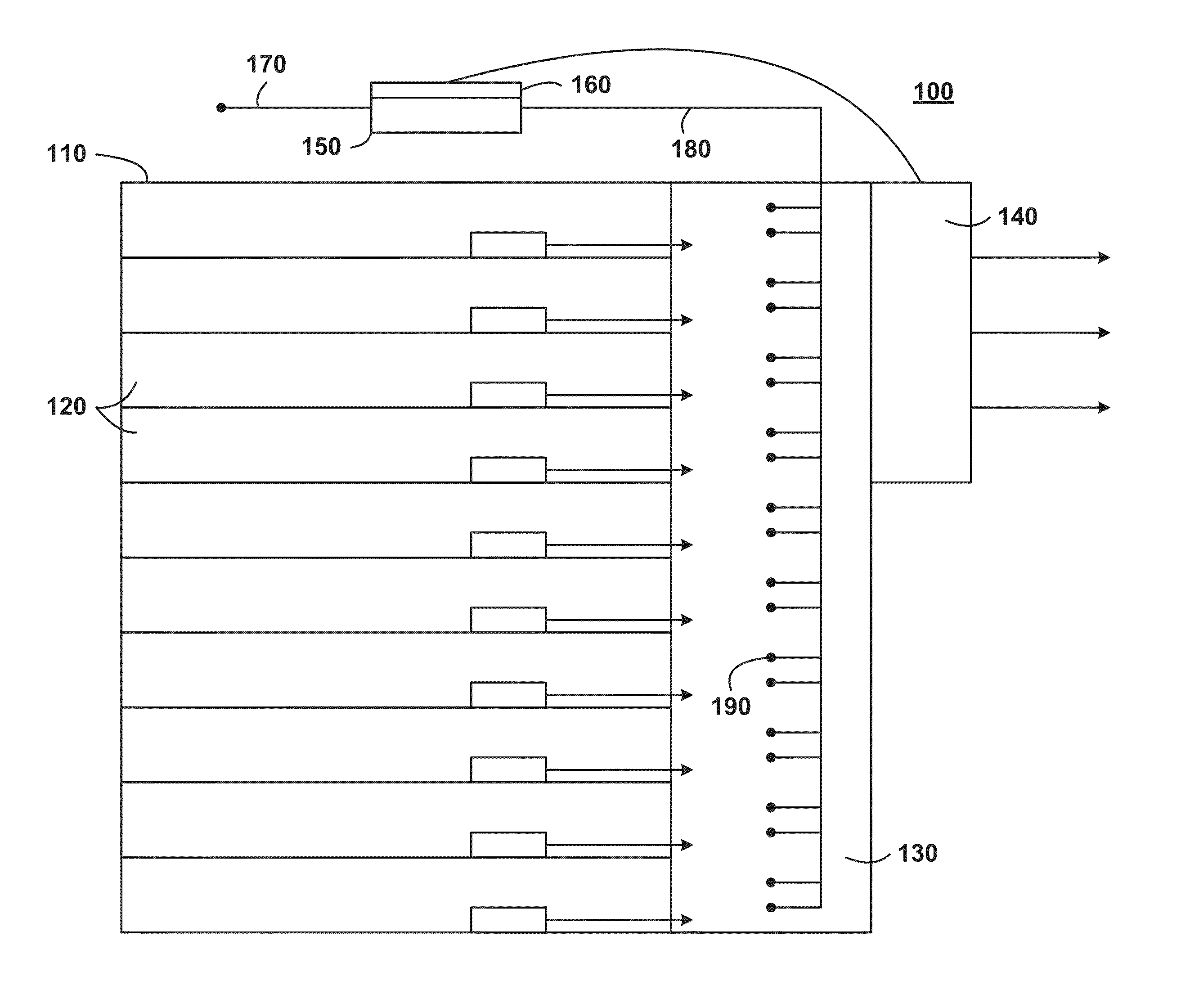
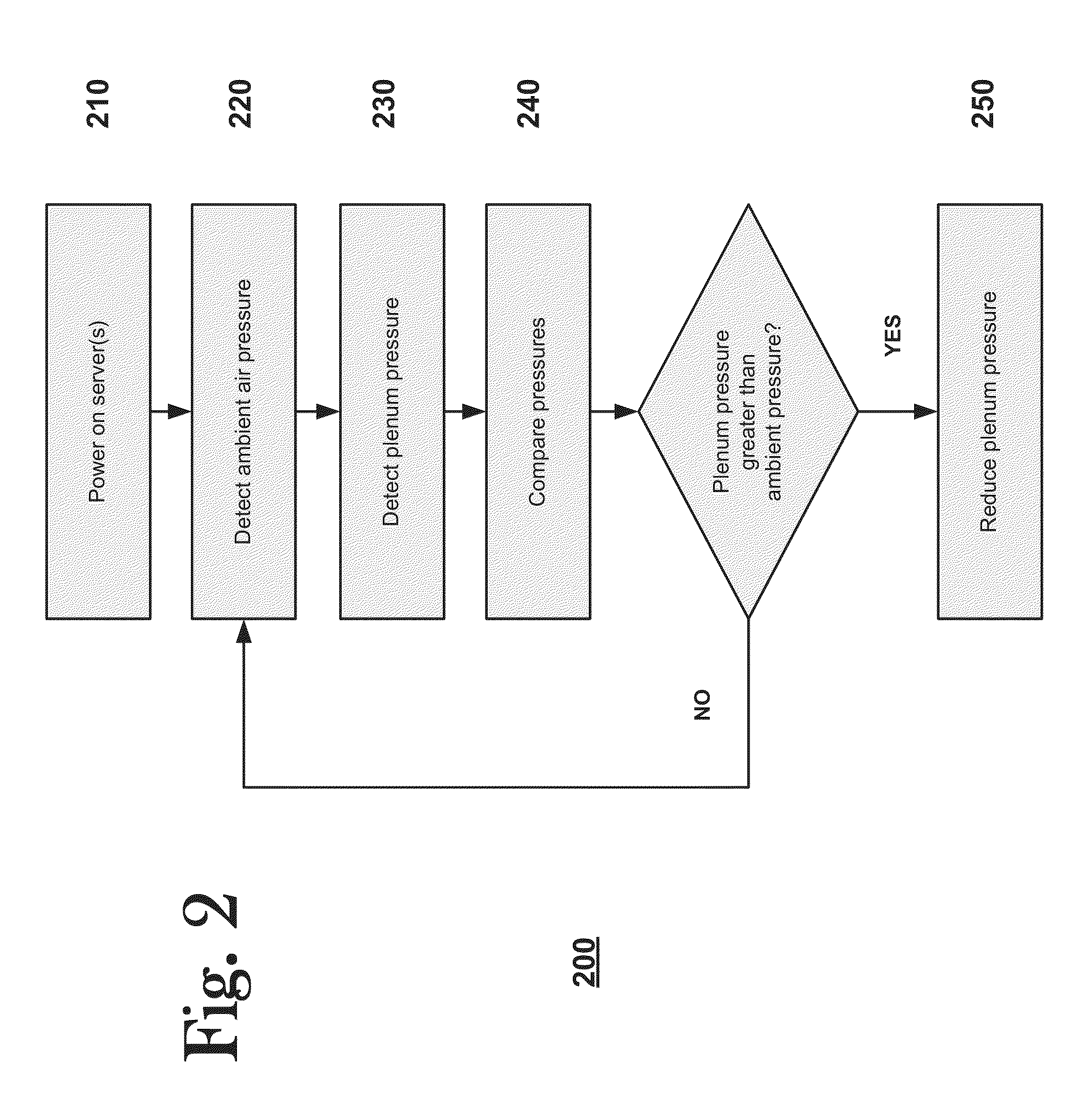
[0020]A pressure-activated server cooling system is provided. The system automatically mitigates flow impedances that naturally build up in server racks. The system does so by detecting and responding to the presence of excess air pressure in the space adjacent to the server outlet vents. The system reduces the pressure in a controlled fashion that allows for energy efficient cooling that does not depend on error-prone temperature readings. Because it is controlled, the system also avoids drawing excess cool air through the servers that would otherwise drop the ΔT rating of the system to a level that customers may deem unacceptable.

[0021]Additionally, because the system is pressure-activated and does not depend on temperature readings, it can be optimized regardless of the ambient temperature present at any given time. By reducing the threat of overheating caused by flow impedances within server racks, the system may also allow data management companies to add more components to the...


PUM


Abstract

A pressure-activated server cooling system includes a server rack that houses one or more servers. The server rack has an interior plenum. A fan is coupled to the server rack that exhausts air from inside the plenum to outside the server rack. A differential pressure sensor collects pressure sensor data and a fan controller, which is operatively connected to the fan and the differential pressure sensor, activates the fan in response to the pressure sensor data. In some embodiments, the fan controller increases the speed of the fan when the pressure sensor data indicates greater than atmospheric pressure in the plenum.

Description

CROSS-REFERENCE TO RELATED APPLICATIONS[0001]The present application claims the priority benefit of U.S. provisional application No. 61 / 841,270 filed Jun. 28, 2013, the disclosure of which is incorporated herein by reference.BACKGROUND OF THE INVENTION[0002]1. Field of the Invention[0003]This disclosure relates to servers. More specifically, it relates to pressure-activated server cooling systems.[0004]2. Description of the Related Art[0005]As companies create and process more and more data, the servers required to handle the data must provide faster access and higher storage capacities. As server processing power continues to increase, so does the heat that is radiated from server processors and other internal circuitry. Battling overheating problems has become a commonplace activity amongst server manufacturers and data management companies.[0006]Servers are typically housed in tray or blade chasses. Several servers are usually stored together within a single “server rack.” Most m...

Claims


Application Information

Patent Timeline
Patent Type & Authority Applications(United States)
IPC IPC(8): H05K7/20
CPCH05K7/20736H05K7/20836
Inventor KINSTLE, III, ROBERT, MICHAEL
Owner HEWLETT-PACKARD ENTERPRISE DEV LP
Learn More