Extended depth of focus for high-resolution optical image scanning

a high-resolution, optical image technology, applied in the field of image scanning system, can solve the problem of small focus area remaining in the target area, and achieve the effect of improving image resolution

Active Publication Date: 2015-01-08
UNIV OF WASHINGTON CENT FOR COMMERICIALIZATION
View PDF1 Cites 44 Cited by
  • Summary
  • Abstract
  • Description
  • Claims
  • Application Information

AI Technical Summary

Benefits of technology

[0005]In many embodiments, improved methods and systems for acquiring and/or projecting images from and/or to a target area are provided. Such methods and systems include an optical fiber assembly which may be driven to scan the target area in a scan pattern. The optical fiber assembly may provide multiple effective light sources that are axially staggered with resp

Problems solved by technology

However, when the light is focused to a small spot, the depth of focus or depth of field of the resulting im

Method used


Image

  • Extended depth of focus for high-resolution optical image scanning
  • Extended depth of focus for high-resolution optical image scanning
  • Extended depth of focus for high-resolution optical image scanning

Examples


Embodiment Construction

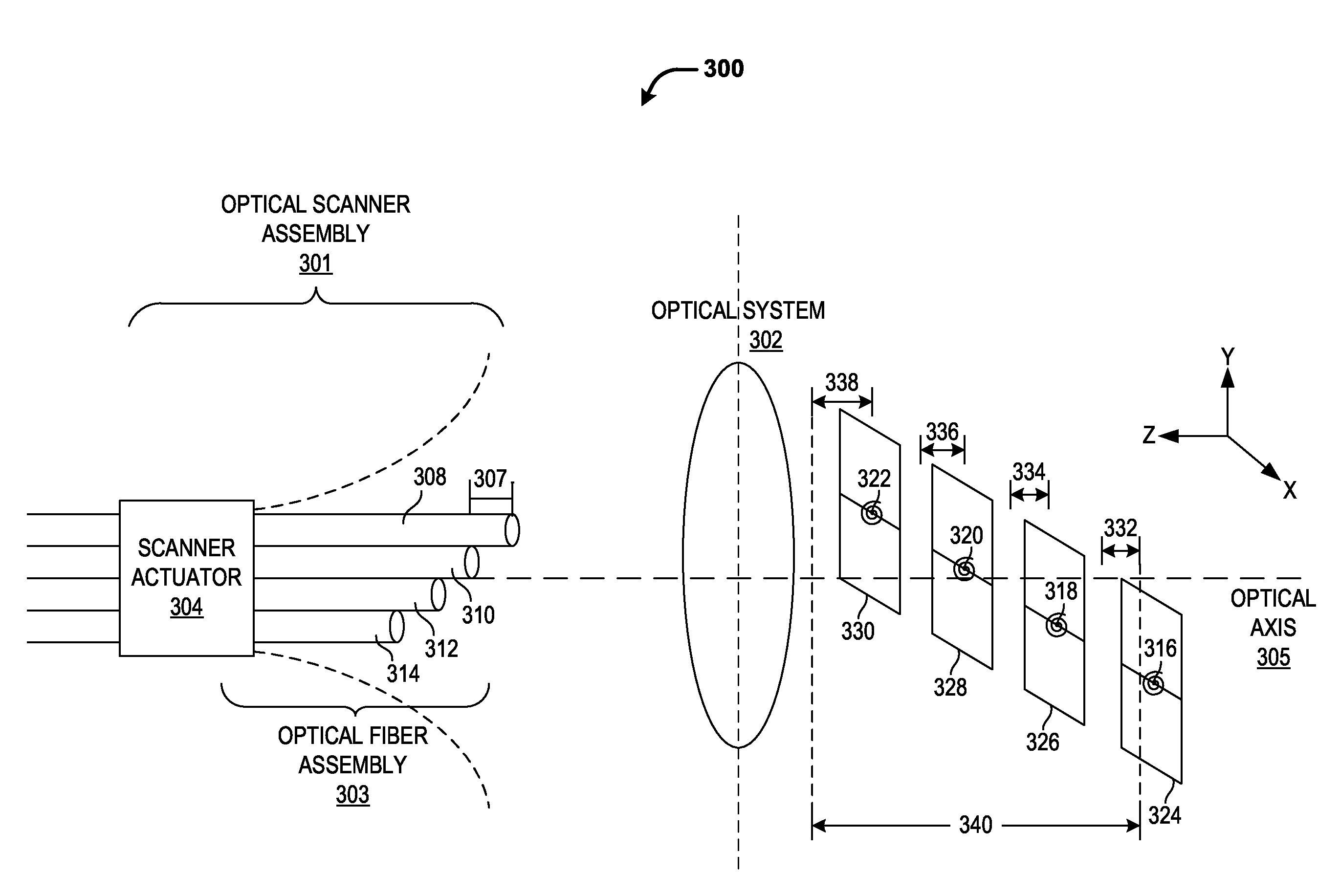
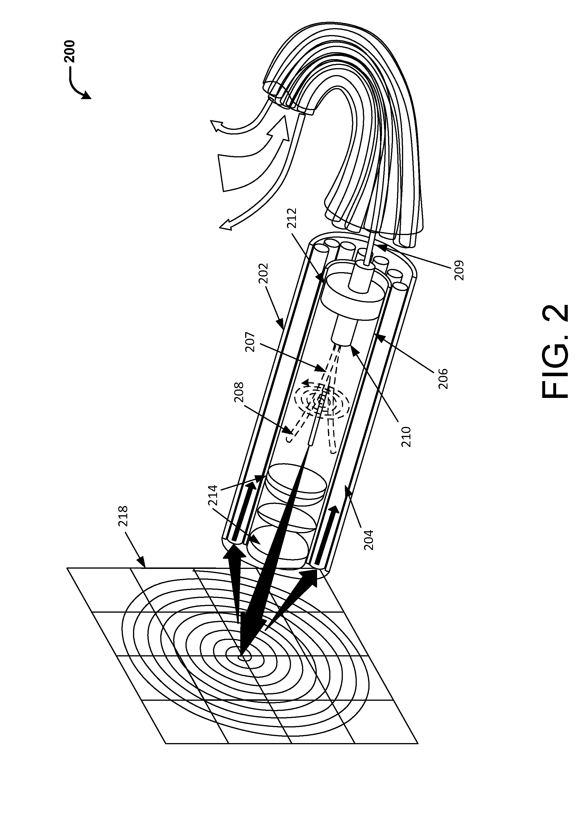
[0023]The present invention provides techniques for creating an extended depth of focus or field while maintaining high image resolution in an image scanning system, such as a scanning fiber endoscope (SFE). Typically, an SFE has a single mode optical fiber that is driven to scan in a scan pattern (e.g., spiral or zigzagged) to deliver illumination in a space-filling area over the surface to be imaged. An optical system (e.g., an objective lens system) between the scanning optical fiber tip and the target area typically defines the image resolution in the SFE and the optical system is typically designed to achieve high spatial resolution while providing shallow depths of focus or field.

[0024]According to an embodiment of the present invention, the single scanning optical fiber in an SFE is replaced with an optical-fiber assembly comprising a plurality of optical fibers. The tips of these optical fibers may be axially staggered relative to an optical system that is configured to focu...


PUM


Abstract

Methods and systems for acquiring and/or projecting images from and/or to a target area are provided. Such a method or system can includes an optical fiber assembly which may be driven to scan the target area in a scan pattern. The optical fiber assembly may provide multiple effective light sources (e.g., via a plurality of optical fibers) that are axially staggered with respect to an optical system located between the optical fiber and the target area. The optical system may be operable to focus and/or redirect the light from the multiple light sources onto separate focal planes. A composite image may be generated based on light reflected from and/or projected onto the separate focal planes. The composite image may have an extended depth of focus or field spanning over a distance between the separate focal planes while maintaining or improving image resolution.

Description

CROSS-REFERENCE[0001]This application claims the benefit of U.S. Provisional Application No. 61 / 599,839, filed Feb. 16, 2012, which application is incorporated herein by reference.STATEMENT AS TO FEDERALLY SPONSORED RESEARCH[0002]This invention was made with the support of the United States government under NIH grant number R33 CA094303 by National Cancer Agency.BACKGROUND OF THE INVENTION[0003]In an image scanning system, a beam of light is typically scanned across a target area and the backscattered or reflected light is modulated in intensity and color to give a pixel at the particular location and time within the scan corresponding to the point on the surface. To increase image resolution or decrease the size of the image pixel, the optical point of interrogation on the surface need to be made sufficiently small. However, when the light is focused to a small spot, the depth of focus or depth of field of the resulting image becomes relatively shallow as well, meaning that only a ...

Claims


Application Information

Patent Timeline
IPC IPC(8): H04N5/232G03B21/14G02B27/40
CPCH04N5/23235H04N5/23212G03B21/142G02B27/40A61B1/07G02B23/2469G02B23/26G02B26/103A61B1/00172A61B1/00167A61B1/00188A61B1/0623H04N23/959H04N23/633H04N23/815
Inventor SEIBEL, ERIC J.SCHOWENGERDT, BRIAN T.
Owner UNIV OF WASHINGTON CENT FOR COMMERICIALIZATION
Why Eureka
Try Eureka