Stand base for a surgical microscope

a technology for surgical microscopes and stand bases, which is applied in the direction of surgical microscopes, instruments, surgical instrument supports, etc., can solve the problems achieve the effects of high user friendliness, increased weight of the stand base, and reliable satisfaction of safety requirements

Active Publication Date: 2015-01-15
CARL ZEISS MEDITEC AG
View PDF11 Cites 2 Cited by
  • Summary
  • Abstract
  • Description
  • Claims
  • Application Information

AI Technical Summary

Benefits of technology

[0033]With the stand base according to the invention for a surgical microscope, it is possible to cover a large variable weight range and at the same time to reliably satisfy the safety requirements of underrun protection.
[0034]In the smallest equipment variant, the stand base can be used without additional weight and without ancillary body. The distance between the underside of the stand base body and the floor may be greater than 12 cm. The safety requirements for underrun protection are thus satisfied with high user friendliness. It is not possible for a foot instep to become wedged. With the next-highest level of development of the mounted surgical microscope, the weight of the stand base can be adapted by fitting one or more weights. Due to the complete integration of the weight modules in a cavity in the stand base body, the distance between the stand base body and the floor can be reliably maintained in this case also.
[0035]With a further necessary increase of the weight of the stand base, an ancillary body can be attached on the underside of the base body. By attaching the ancillary body to the underside of the base body, a new distance is given between the underside of the ancillary body and the floor. In this case, the distance may be less than 3.5 cm and would therefore satisfy a further safety requirement of underrun protection in a reliable and user-friendly manner.
[0036]Since the ancillary body in turn contains a hollow space for at least one weight module, a further margin for the adaptation of the weight of the stand base is advantageously provided. The cavity in the base body and the hollow space in the ancillary body is advantageously formed such that identical weight modules can be introdu

Problems solved by technology

Due to the large distance, it is therefore impossible for the instep

Method used


Image

  • Stand base for a surgical microscope
  • Stand base for a surgical microscope
  • Stand base for a surgical microscope

Examples


first embodiment

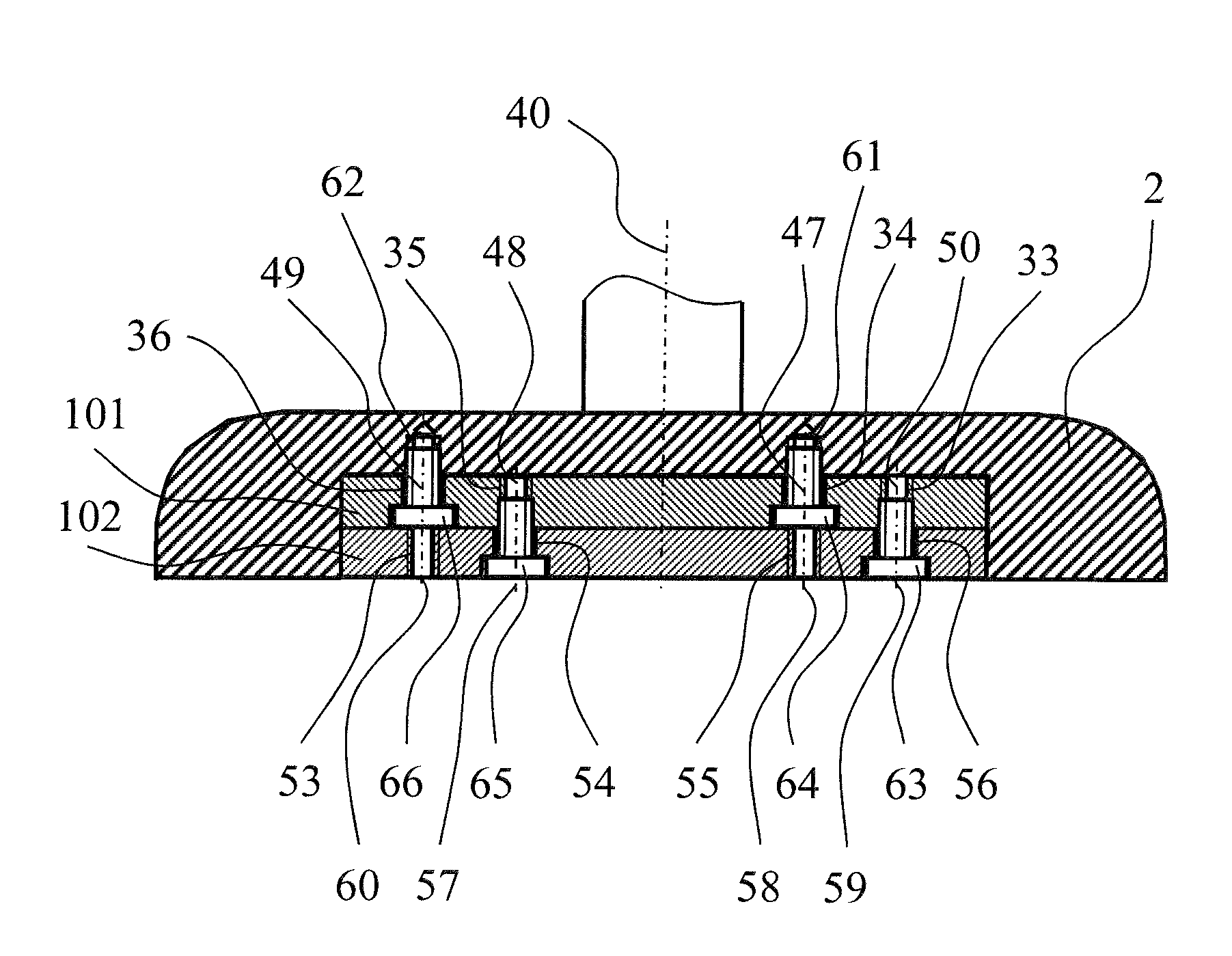
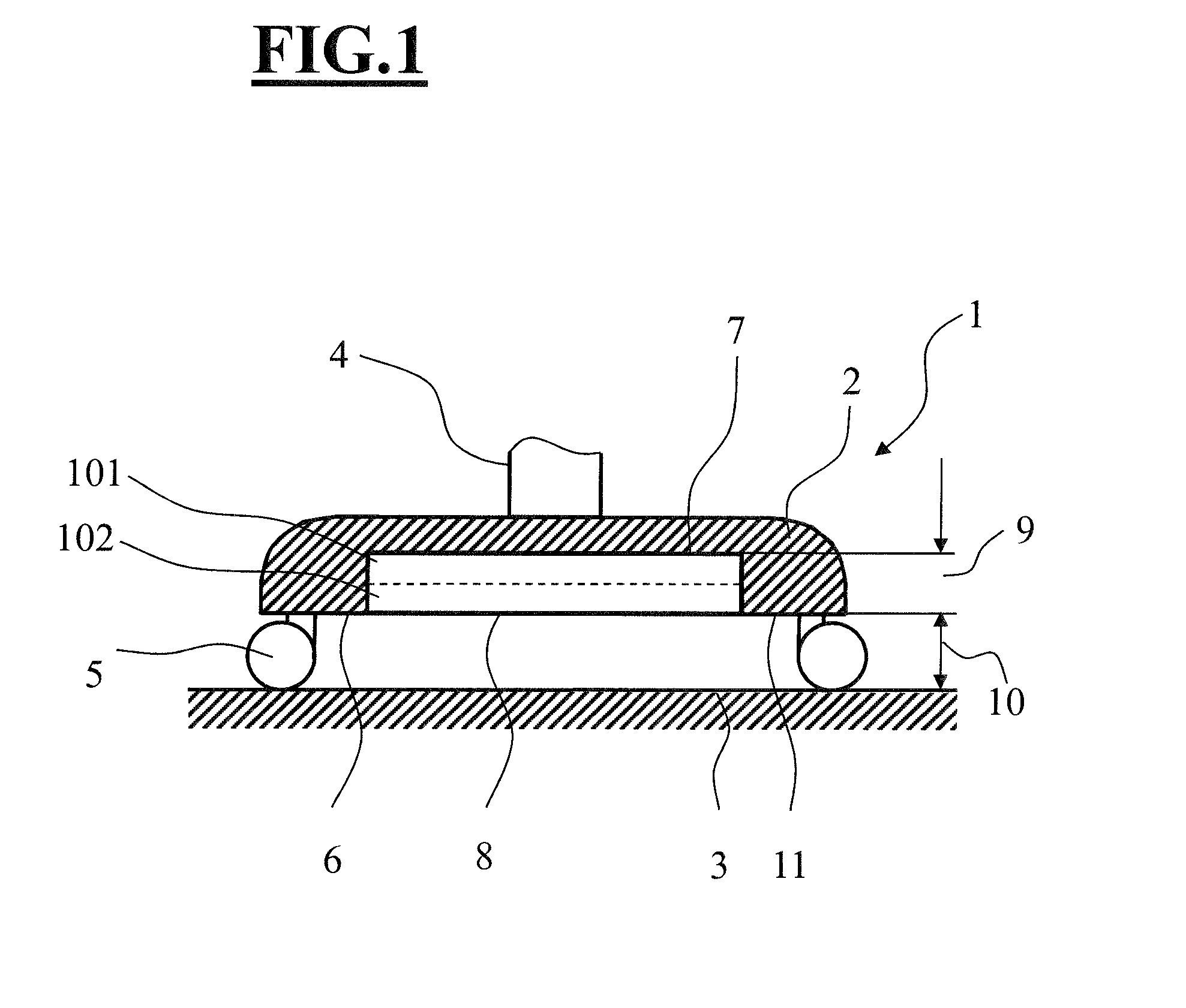
[0044]FIG. 1 is a side elevation view, in section, showing a stand base 1. The core of the stand base 1 forms a base body 2. The base body 2 can be configured in any form. For example, a cylindrical, cuboidal, star-shaped or “H”-shaped design as viewed from above is conceivable. A stand post 4 is attached to the upper side of the base body 2, and a retaining device (not shown here) for a surgical microscope is fastened to the stand post. The underside 6 of the base body 2 is substantially parallel to a floor 3. The floor 3 constitutes a substantially planar surface, on which the stand base 1 can be positioned or on which the stand base 1 can be moved. The underside 6 has a receiving device 11. The receiving device 11 enables the attachment of an ancillary body (not shown here). The receiving device 11 may additionally have bores, threads or recesses (not shown here), for example a milled groove.

[0045]The stand base 1 can be equipped on the underside 6 thereof with three to five, pre...

second embodiment

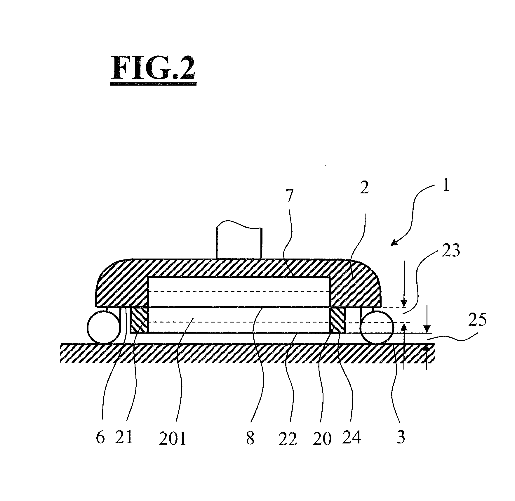
[0054]FIG. 2 is a side elevation view, in section, of the stand base 1 of the invention with an attached ancillary body 20.

[0055]FIG. 2 shows the inventive stand base 1 from FIG. 1. The ancillary body 20 is attached to the receiving device 11 on the underside 6 of the base body 2. The ancillary body 20 can be fastened to the receiving device 11 of the base body 2 by screwing, adhesive bonding, riveting or another known fastening method. The ancillary body 20 can be permanently fastened or can be attached to the base body 2 by a releasable connection. However, the ancillary body 20 is preferably fastened to the underside of the base body 2 with threaded fasteners.

[0056]Due to the attachment of the ancillary body 20, the distance 25 between the underside 24 of the ancillary body 20 and the floor 3 is changed such that the provisions of standard “DIN EN 60601-1 3ed” for avoiding foot injuries (underrun protection) are satisfied. In this exemplary embodiment, the distance 25 is less tha...


PUM


Abstract

The stand base is for a surgical microscope. The stand base is for setting up on a floor configured as a planar surface and includes at least a first weight module; a base body defining an underside and accommodating the first weight module; a support arrangement connected to the base body and supporting the stand base with at least three support points in contact engagement with the floor to permit setting up the stand base; the support points conjointly defining a support plane whereat the support points are in contact engagement with the floor; the underside of the base body facing toward the support plane; an ancillary body; the base body having a receiving arrangement in the underside for releasably accommodating the ancillary body; and, the underside of the base body and the support plane conjointly defining a smallest spacing therebetween which is greater than 10 cm.

Description

CROSS REFERENCE TO RELATED APPLICATIONS[0001]This application is a continuation application of international patent application PCT / EP2013 / 000765, filed Mar. 14, 2013, designating the United States and claiming priority from German application 10 2012 006 409.8, filed Mar. 30, 2012, and the entire content of both applications is incorporated herein by reference.BACKGROUND OF THE INVENTION[0002]Surgical microscope systems often comprise a surgical microscope, a retaining system to which the surgical microscope is fastened, and a stand base, which forms the base of this retaining system. Since surgical microscopes are available in various levels of equipment, the weight of the surgical microscope changes depending on the level of equipment. A weight change of the surgical microscope has effects on the retaining system and the stand base of the retaining system. In order to avoid a tilting of the stand base in any case, this is therefore to be formed so as to be as heavy as possible. A...

Claims


Application Information

Patent Timeline
IPC IPC(8): G02B21/24F16M3/00F16M11/00G02B21/00
CPCG02B21/24F16M11/00G02B21/0012F16M3/00F16M11/42F16M2200/08A61B90/50A61B90/20A61B2090/504F16M11/20G02B7/001A61B2090/5025E04H12/2238
Inventor BEUTELSPACHER, HANNAKOENIG, FRANK
Owner CARL ZEISS MEDITEC AG
Why Eureka
Try Eureka