Frequency responsive charging system and method

a charging system and frequency technology, applied in charging stations, electric vehicle charging technology, transportation and packaging, etc., can solve the problems of powerplants responding relatively slowly, grid frequency will change, and the speed of grid frequency correction in this manner is also very slow

Inactive Publication Date: 2015-01-15
AEROVIRONMENT INC
View PDF4 Cites 32 Cited by
  • Summary
  • Abstract
  • Description
  • Claims
  • Application Information

AI Technical Summary

Problems solved by technology

When there is an imbalance between the generation and load, the grid frequency will change.
However, powerplants resp

Method used


Image

  • Frequency responsive charging system and method
  • Frequency responsive charging system and method
  • Frequency responsive charging system and method

Examples


Embodiment Construction

[0016]With utility power grids when an imbalance exists between the power generation and the load the rate of change of frequency is proportional to the amount of the imbalance. Rotating generators tied to the grid have inertia which determines the rate of change of frequency for a given imbalance of generation and load. The more inertia of the generators, the slower the rate of change of frequency will be will be for a given imbalance of power.

[0017]Grid operators may run control loops to seek to regulate the grid frequency. These loops use as input the difference between the instantaneous grid frequency and the target frequency (usually 60 Hz in the US). These control loops are implemented with a grid ancillary service called frequency regulation (or often just: regulation). Regulation ancillary services allow the grid operator to directly control the power output or load of resources on the grid that have contracted to provide this service.

[0018]Typically regulation commands are ...


PUM


Abstract

In some embodiments, the present invention includes the use of one or more electric power supply system, or systems, and the electric vehicle, or vehicles, connected thereto, to provide load-based utility grid frequency regulation by varying the amount of power drawn by the vehicle or vehicles.

Description

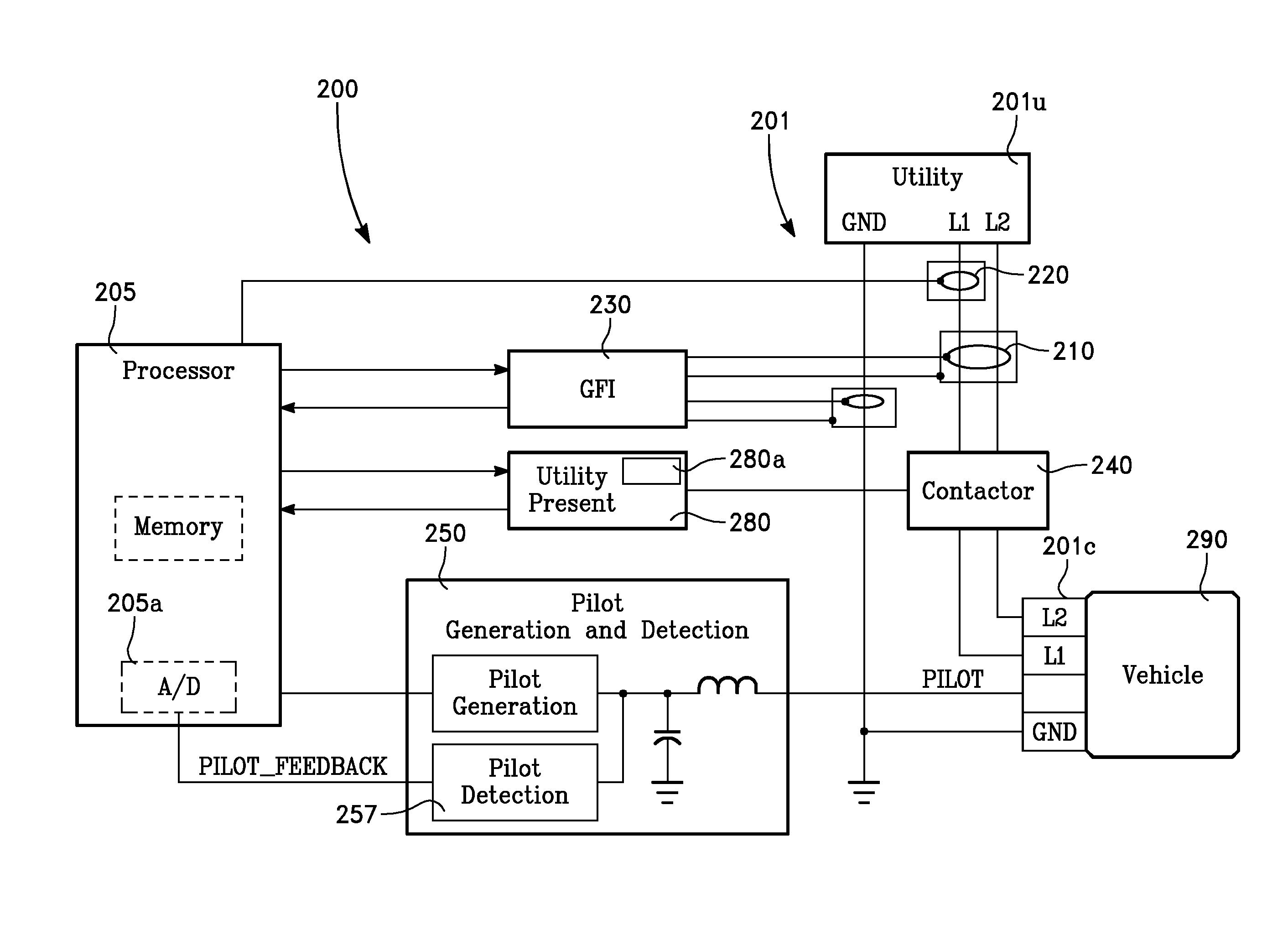
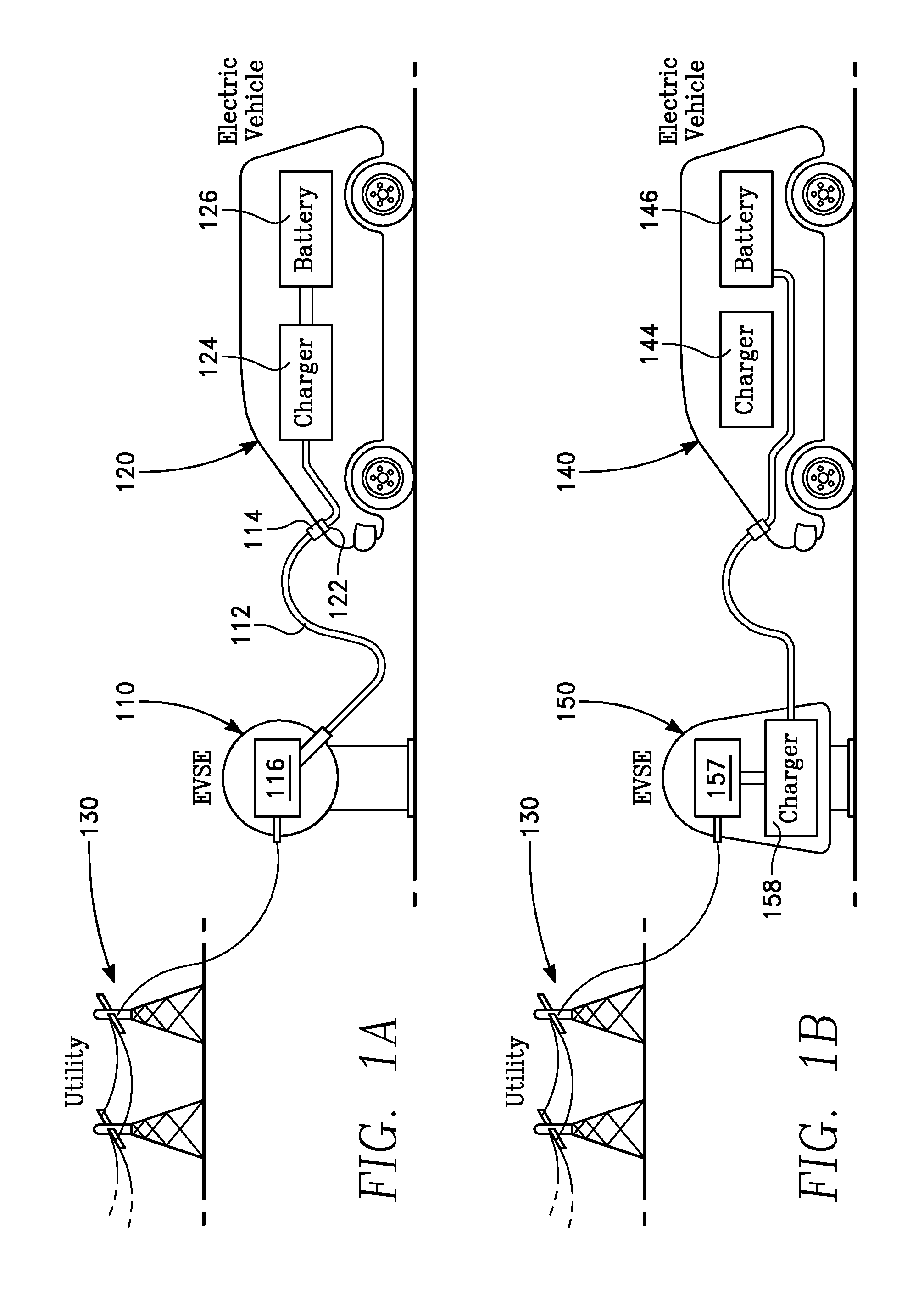
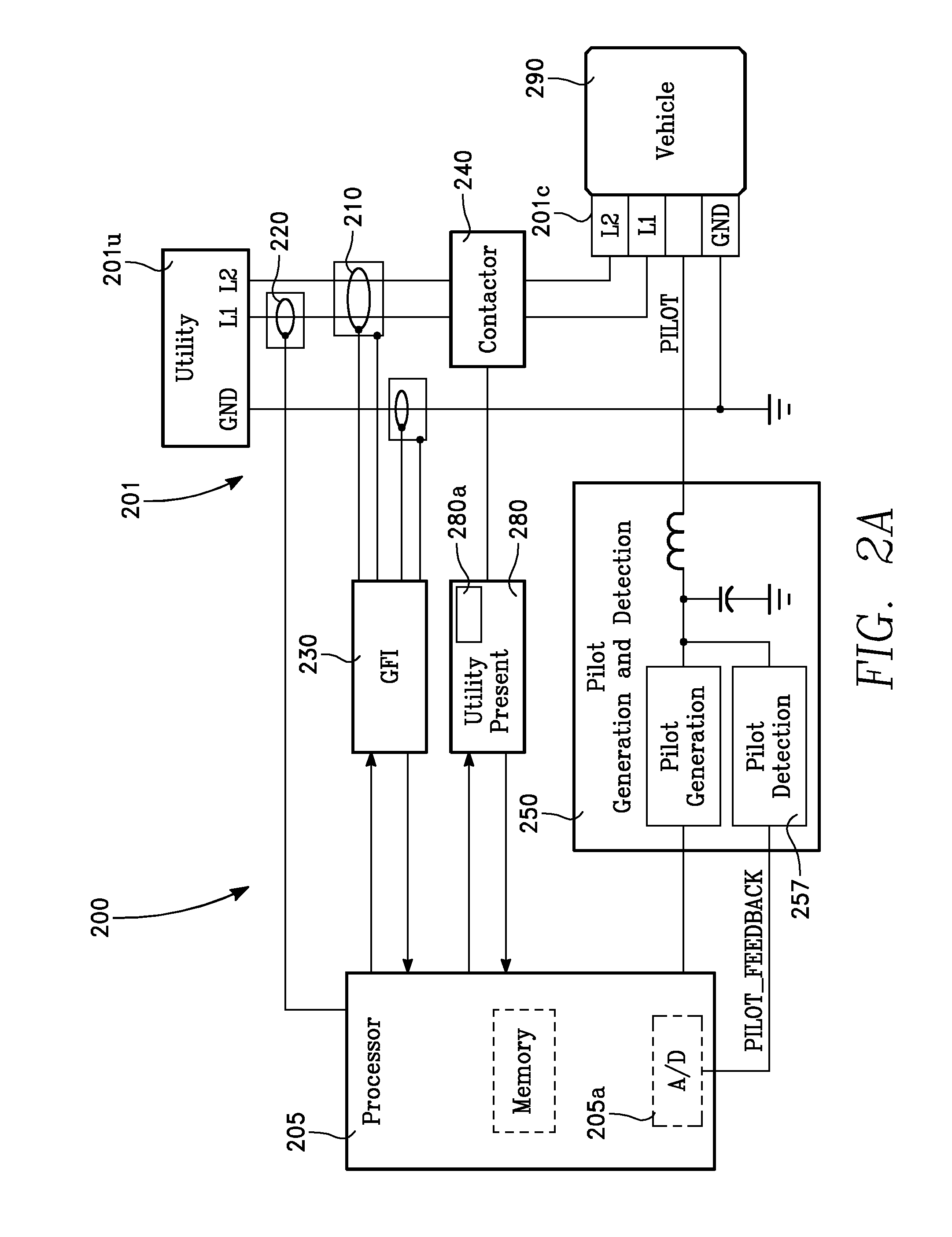
CROSS REFERENCE TO RELATED APPLICATION[0001]This application claims to the benefit of U.S. Provisional Patent Applications Ser. No. 61 / 617,039, filed Mar. 28, 2012, by Brooks et al., which is herein incorporated by reference in its entirety.BACKGROUND OF THE INVENTION[0002]Utility grids require that the power generation and loads are in balance in order to keep the frequency constant. When there is an imbalance between the generation and load, the grid frequency will change. Grid frequency regulation can be performed by powerplants varying their generation output up and down from a nominal value. However, powerplants respond relatively slowly to regulation commands and thus correcting the grid frequency in this manner is also very slow.BRIEF DESCRIPTION OF THE DRAWINGS[0003]FIGS. 1A-B show an EVSE connected to an electric vehicle and to the utility grid in accordance with at least one embodiment of the present invention.[0004]FIGS. 2A-B show block diagrams of electric vehicle supply...

Claims


Application Information

Patent Timeline
IPC IPC(8): B60L11/18
CPCB60L11/1816B60L11/1844B60L2210/30B60L11/1811Y04S10/126Y04S30/12B60L2240/547B60L2240/549B60L2240/80Y02T10/7072Y02T90/14Y04S30/14B60L55/00B60L53/63B60L53/65B60L53/18H02J3/242H02J3/322Y02E60/00Y02T10/72Y02T90/12Y02T90/167Y02T10/70Y02T90/16
Inventor BROOKS, ALEXANDER NELSONBERMAN, SCOTT GARRETHAMMERVOLD, NICHOLAS
Owner AEROVIRONMENT INC
Why Eureka
Try Eureka