Charge/discharge control apparatus

a control apparatus and discharge device technology, applied in the direction of electric devices, process and machine control, data processing applications, etc., can solve the problems of future increase in the number of installations using storage batteries, timer control technique limitation, and the inability to optimize the whole power installation, so as to reduce the flat electric power rate

Active Publication Date: 2010-03-25
HITACHI LTD
View PDF7 Cites 190 Cited by
  • Summary
  • Abstract
  • Description
  • Claims
  • Application Information

AI Technical Summary

Benefits of technology

[0019]Those means enables to draw up a socially-suitable charge / discharge plan within a range not giving inconvenience to a user, while based on the charge / discharge reward information. For example, if a user is scheduled to drive an electric vehicle at a given time on the following day, a charging plan can be created within a range not negatively affecting the time of departure on the following day with at least a partial contribution to the environment.
[0020]As described above, the charge / discharge reward information is broadcast, even if a user does not conduct a charge / discharge action as originally planned because of an accidental event or the like. This enables at least a partial contribution to the environment.
[0021]Even such a partial contribution has an effect of encouraging a user to willingly participate in the program. The charge / discharge control apparatus can obtain a degree of contribution made by each user, from the external facility because the charge / discharge control apparatus has the means for monitoring or reporting whether or not a charge / discharge has been actually conducted. The charge / discharge control apparatus can reduce a flat electric power rate regarding a power usage amount used for a charging and provide various merits to the users.

Problems solved by technology

Of the conventional techniques described above, the technique using a timer control has, however, a problem of having a difficulty in dealing with a future increase in the number of installations using storage batteries.
The conventional technique using a timer control has a limitation in that optimization of the whole power installations is attempted by changing timer-controlled parameters via off-line operations on a case-by-case basis.
In reality, however, a user does not always conduct a charge / discharge action as originally planned because of an accidental event or the like.
It is therefore difficult that all of the users send all of their charging requests to the external facility without fail.
Any of the related arts described above have a difficulty in offering a social program for leading a customer to a desired charge / discharge action.
Otherwise, such a charging gives inconvenience to the user.

Method used


Image

  • Charge/discharge control apparatus
  • Charge/discharge control apparatus
  • Charge/discharge control apparatus

Examples


first embodiment

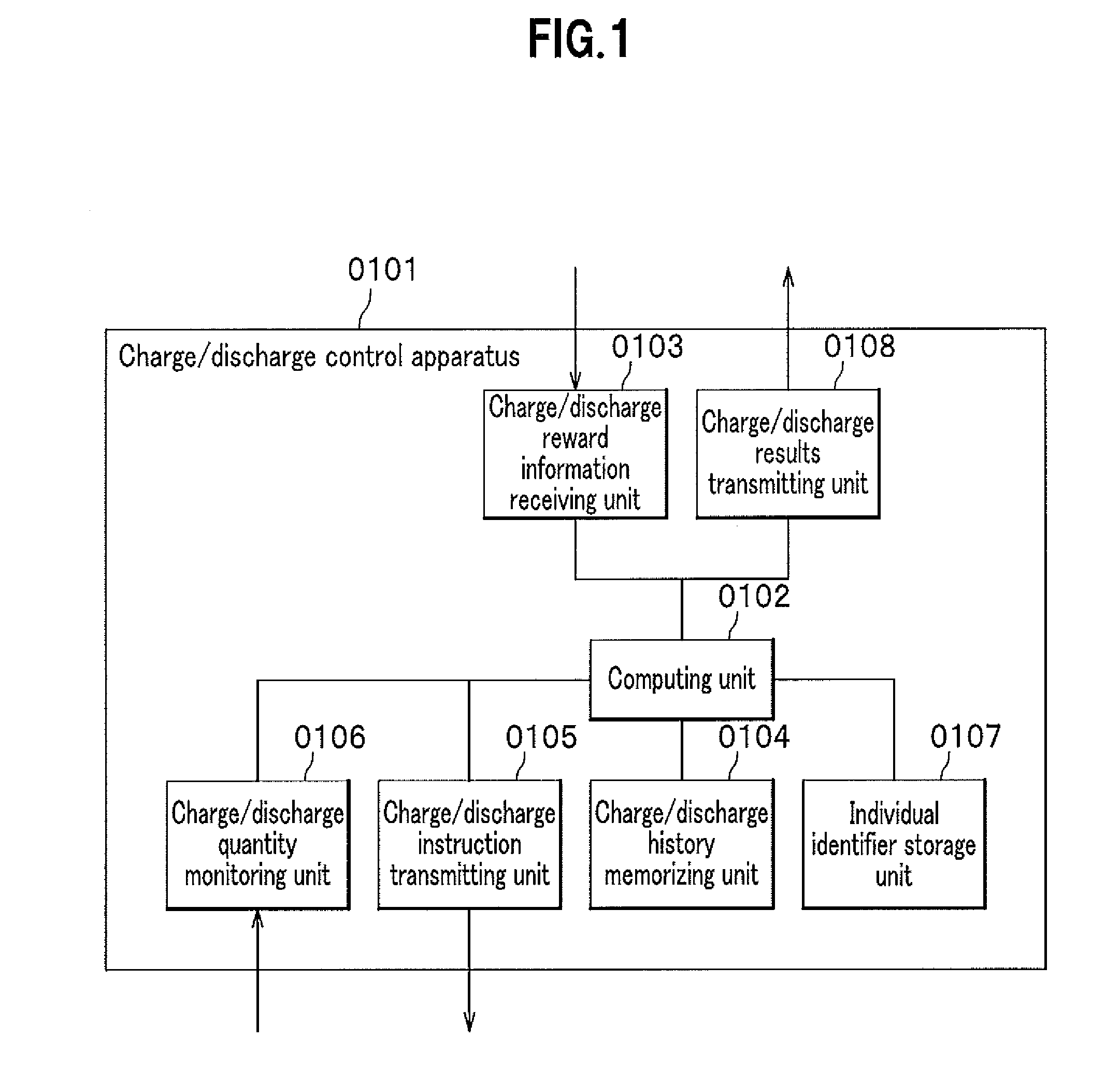
[0041]FIG. 1 shows a functional configuration of a charge / discharge control apparatus according to a first embodiment. A charge / discharge control apparatus 0101 includes a computing unit 0102 and various input and output units for coordinating with an external facility. A charge / discharge reward information receiving unit 0103 receives charge / discharge reward information which quantitatively represents a degree of contribution to society made by a charge / discharge action (a degree of positive or negative influence on society) for each time zone, from a computer as the external facility. A memory unit not shown of the charge / discharge control apparatus 0101 memorizes the received charge / discharge reward information.

[0042]The computing unit 0102 estimates an estimated usage start time and an estimated used power quantity of a power installation targeted for use, based on the charge / discharge reward information as well as history information stored in a charge / discharge history memoriz...

second embodiment

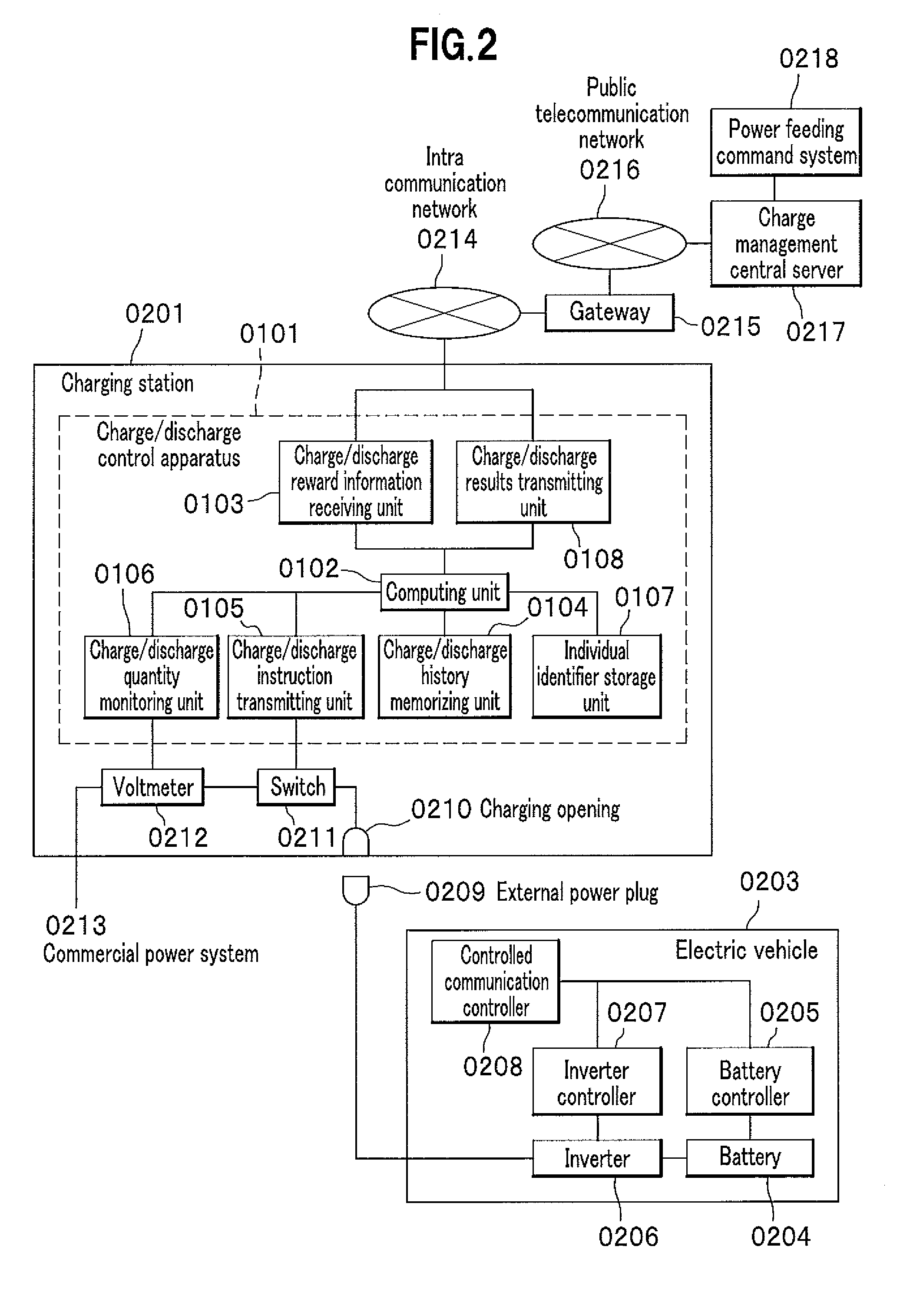
[0076]A second embodiment describes a system in which a charge / discharge apparatus of the present invention is mounted in a charge ground-based charging station, and the charge / discharge apparatus cooperates with a dispatch control system which is a server used by an operator of managing electrical vehicles for business use, to thereby manage a charge / discharge action of the electric vehicles for business use. In the system, it is assumed that a number of electric vehicles for business use are present and that any of the electric vehicles can be connected to the charging station. FIG. 11 shows a configuration of the system. The configuration and processing in the second embodiment are similar to those in the first embodiment. Next is described the second embodiment focusing on operations different from those in the first embodiment.

[0077]The charge station 0201 includes a vehicle information input unit 1101 for inputting an ID number for identifying the electric vehicle 0203. The ve...

third embodiment

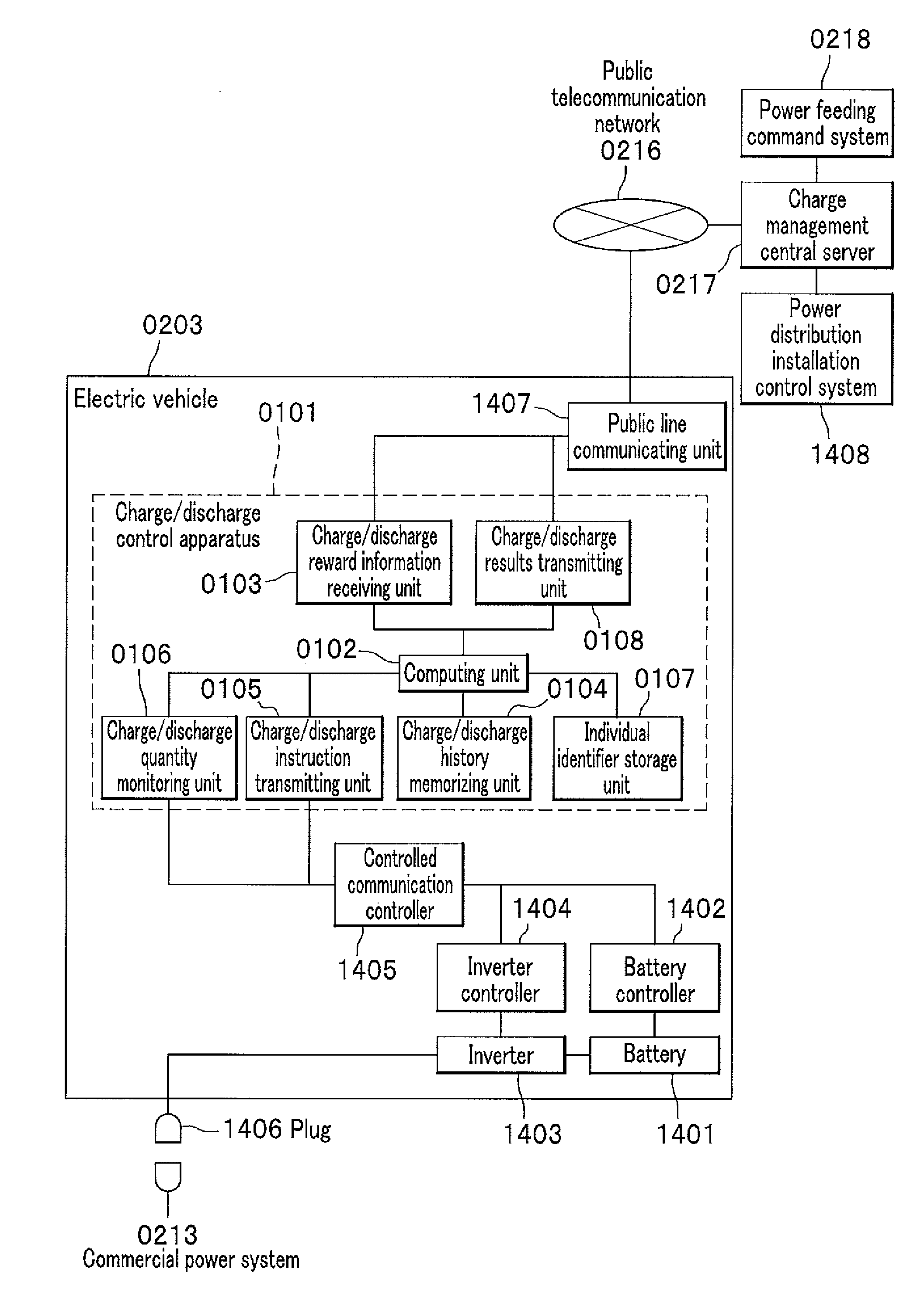
[0080]A third embodiment describes a system in which a charge / discharge apparatus of the present invention is mounted in an electric vehicle, and the charge / discharge apparatus manages a charge / discharge action of the electric vehicle. Further, the system in this embodiment has a configuration in which a charging is managed according to circumstances by region by cooperating with a power distribution installation control system or the like, if the electric vehicle freely travels over a wide region. FIG. 14 shows a functional configuration of the system. The configuration and processing in the third embodiment are similar to those in the first embodiment. Next is described the third embodiment focusing on operations different from those in the first embodiment.

[0081]In this embodiment, a set of power conversion devices for use in conducting a charging / discharging is mounted in the electric vehicle 0203. More specifically, the electric vehicle 0203 is equipped with: a battery 1401; a ...


PUM

PropertyMeasurementUnit
timeaaaaaaaaaa
power quantityaaaaaaaaaa
distanceaaaaaaaaaa

Abstract

A charge/discharge control apparatus includes: a charge/discharge reward information receiving unit for receiving charge/discharge reward information representing a reward given to a charge/discharge action of a customer and a restriction in conducting a charging/discharging from a charge management central server; a computing unit for creating a charge/discharge plan including a total charging quantity in a time zone and an estimated use start time of an electric vehicle such that a reward is maximized, based on the charge/discharge reward information; a charge/discharge instruction transmitting unit for instructing the electric vehicle to start or finish a charging/discharging according to the charge/discharge plan; a charge/discharge quantity monitoring unit for monitoring the charging/discharging; and a charge/discharge results transmitting unit for transmitting results of monitored charging/discharging including contents of the conducted charging/discharging and individual identification information for identifying itself, to a charge management central server.

Description

CROSS REFERENCE TO RELATED APPLICATIONS[0001]This application claims the benefit of Japanese Patent Application No. 2008-246550 filed on Sep. 25, 2008, the disclosure of which is incorporated herein by reference.BACKGROUND OF THE INVENTION[0002]1. Field of the Invention[0003]The present invention relates to a technique of indirectly controlling a start time or an end time of a charge / discharge and a quantity of the charge / discharge so as to achieve a charge / discharge plan of an electric storage installation using a secondary battery connected to a wide-area power system, in particular, so as to improve an energy consumption performance and a social environmental performance as a whole power system in terms of a number of storage batteries freely connected in parallel and disconnected by end users.[0004]2. Description of the Related Art[0005]Electric power installations using storage batteries, that is, electric storage installations have been recently expected to come into wide use ...

Claims


Application Information

Patent Timeline
Patent Type & Authority Applications(United States)
IPC IPC(8): G06Q30/00H02J7/00G06F7/00B60L3/00B60L11/18G06Q50/00G06Q50/06H01M10/44H02J3/00H02J3/14H02J3/32H02J3/38H02J7/02H02J7/34
CPCB60L3/12Y02E60/721B60L11/1838B60L11/184B60L11/1842B60L11/1846B60L11/1848B60L11/1862B60L2230/16B60L2260/56G06Q30/0207G06Q50/06H02J3/32Y02T10/7005Y02T10/7044Y02T10/705Y02T10/7088Y02T90/121Y02T90/128Y02T90/14Y02T90/163Y02T90/169Y04S10/126Y04S30/14B60L11/1816B60L53/14B60L53/60B60L53/64B60L55/00B60L53/65B60L53/665B60L53/305H02J2310/48H02J3/322Y02E60/00Y02T10/70Y02T10/7072Y02T90/12Y02T90/167Y02T90/16
Inventor SATO, YASUOMATSUZAKI, TAKAOWATANABE, MASAHIROTOMITA, YASUSHI
Owner HITACHI LTD
Why Eureka
Try Eureka