Eureka AIR delivers breakthrough ideas for toughest innovation challenges, trusted by R&D personnel around the world.

Image generation device, camera device, image display device, and image generation method

a technology of image display device and image generation method, which is applied in the field of image generation device, camera device, image display device, image generation method, can solve the problem of difficult to see display image, and achieve the effect of suppressing the rapid change of the orientation of the targ

Active Publication Date: 2015-01-15
PANASONIC INTELLECTUAL PROPERTY MANAGEMENT CO LTD
View PDF3 Cites 7 Cited by
  • Summary
  • Abstract
  • Description
  • Claims
  • Application Information

AI Technical Summary

Benefits of technology

The technical effect of this patent is to reduce the rapid change in the orientation of a target in a video clip during display.

Problems solved by technology

However, an orientation of the target in the clip image to be displayed is changed largely and rapidly by an influence of processing for rotating the clip image, and there is a problem that the display image is hard to be seen.

Method used


Image

  • Image generation device, camera device, image display device, and image generation method
  • Image generation device, camera device, image display device, and image generation method
  • Image generation device, camera device, image display device, and image generation method

Examples


first embodiment

[0026]A configuration of an image processing system of a first embodiment of the present invention will be explained by referring to the attached drawings.

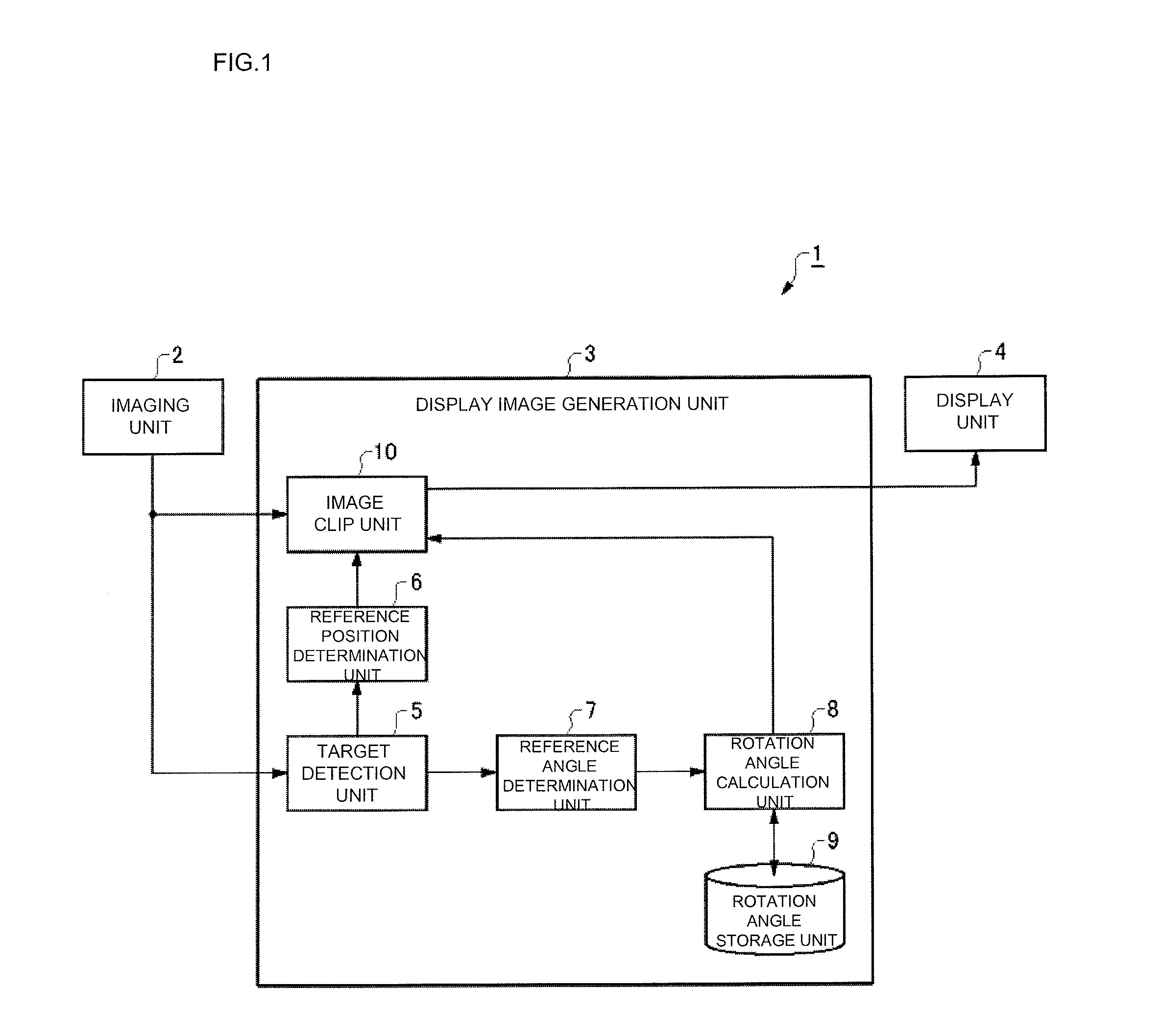
[0027]FIG. 1 is a block diagram illustrating a configuration of the image processing system of the first embodiment.

[0028]As illustrated in FIG. 1, the image processing system 1 is provided with an imaging unit 2 for taking an area image, a display image generation unit 3 for generating a display image by applying predetermined image processing which will be described later to an image taken by the imaging unit 2, and a display unit 4 for displaying the display image generated by the display image generation unit 3.

[0029]The imaging unit 2, the display image generation unit 3, and the display unit 4 may be constituted as a single device or constituted by separate devices. Moreover, it may be so configured that the imaging unit 2 and the display image generation unit 3 are constituted as a single camera device, and the display unit...

second embodiment

[0051]Subsequently, an image processing system of a second embodiment of the present invention will be explained.

[0052]In this embodiment, a difference from the first embodiment will be mainly explained. Unless particularly referred to here, a configuration and an operation of this embodiment are similar to those in the first embodiment.

[0053]FIG. 4 is a block diagram illustrating a configuration of the image processing system of the second embodiment, and FIG. 5 is an explanatory view of area determination in the second embodiment of the present invention. The display image generation unit 3 of the image processing system 1 in this embodiment is provided with a distance calculation unit 11 and an area determination unit 12 in addition to the configuration illustrated in the first embodiment.

[0054]As illustrated in FIGS. 4 and 5, the distance calculation unit 11 calculates the distance r between the position O (photograph reference position) corresponding to the imaging unit 2 in th...


PUM


Abstract

A camera device is provided with: an imaging unit for generating an area image obtained by shooting an area from above; and a display image generation unit for generating a display image of a target moving in the area using a clip image which is clipped from the area image. In this case, a rotation angle of a current frame is calculated on the basis of the rotation angle of the previous frame and a reference angle of the current frame. As a result, a rapid change in an orientation of the target displayed in the display image can be suppressed.

Description

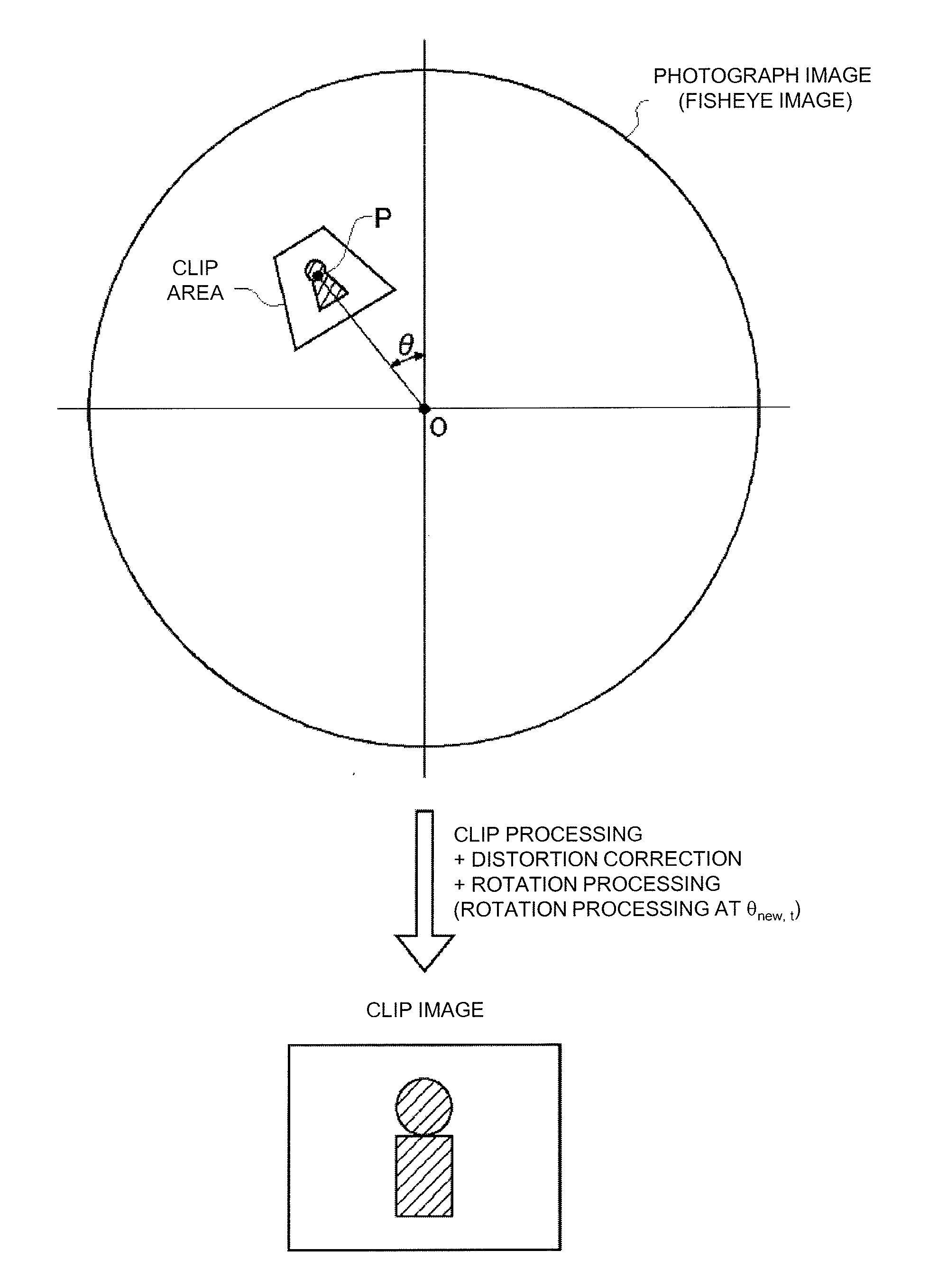
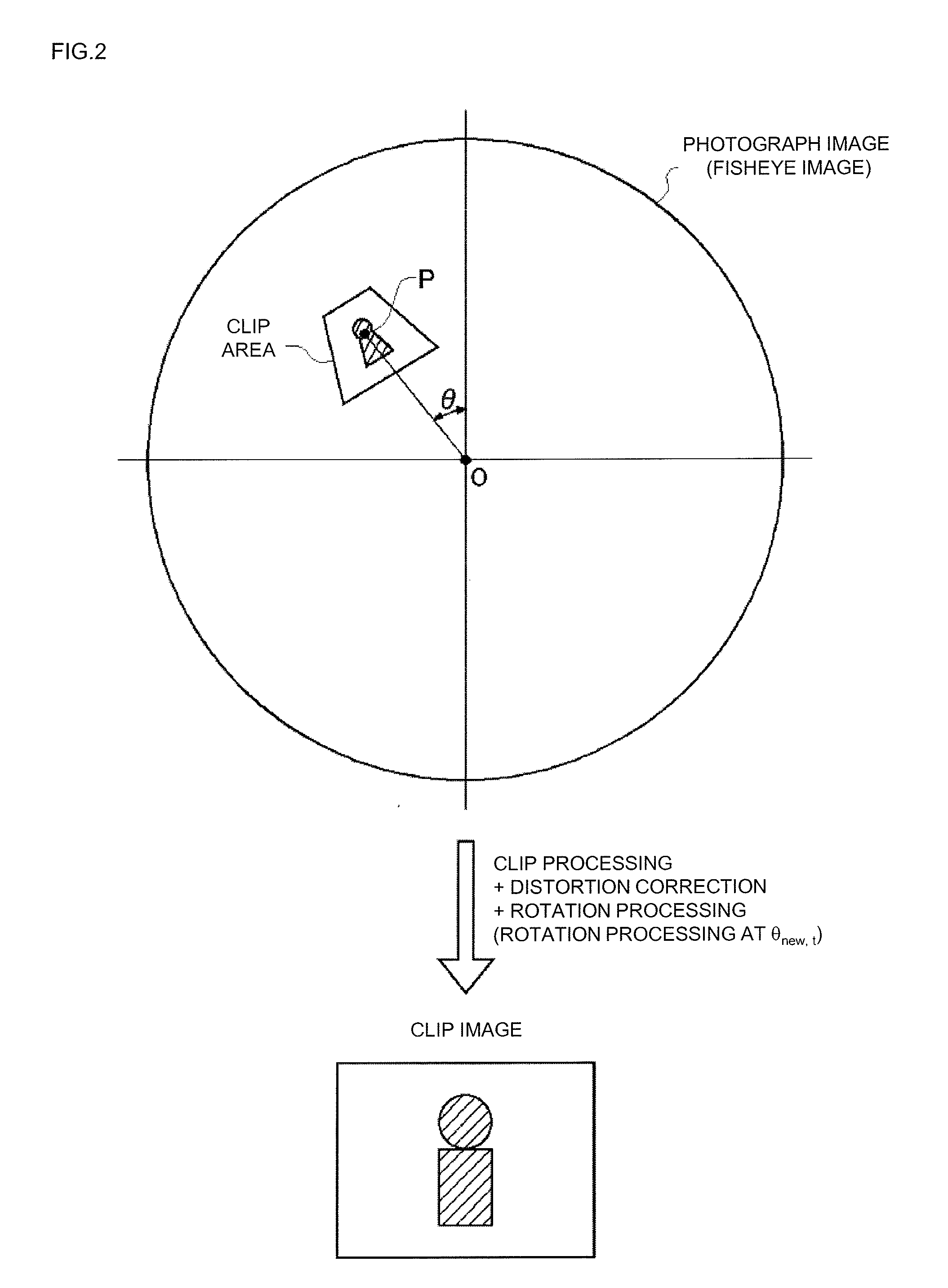
TECHNICAL FIELD[0001]The present invention relates to an image generation device, a camera device, an image processing system, and an image generation method for generating an output image for display by using a clip image clipped from a wide-angle image taken by a camera.BACKGROUND OF THE INVENTION AND RELATED ART[0002]A system for generating an output image for display by processing a wide-angle image taken by a camera provided with a wide-angle lens such as a fisheye lens and the like has been proposed (see Patent Literature 1 to Patent Literature 3, for example). As one of those image processing systems, a system for generating a clip image including a target from the image and displaying / outputting it is known.[0003]As illustrated in FIG. 7, when a predetermined area is to be clipped from a image obtained by using a wide-angle lens such as a fisheye lens, the target is inclined in accordance with a position of the target. Thus, when a clip image is to be generated from the imag...

Claims


Application Information

Patent Timeline
Patent Type & Authority Applications(United States)
IPC IPC(8): G06T3/00H04N5/232G06K9/52H04N5/262
CPCG06K9/52H04N5/23296G06T2210/22H04N5/23229G06T3/0018H04N5/2628H04N7/183G06T3/00G06V20/56H04N23/80H04N23/698G06T5/80H04N23/69G06T3/047
Inventor KUWADA, JUNYA
Owner PANASONIC INTELLECTUAL PROPERTY MANAGEMENT CO LTD
Why Eureka
Eureka Blog
Learn More