
Air supply system

a technology of air supply system and air supply, which is applied in the direction of machines/engines, liquid fuel engines, positive displacement liquid engines, etc., can solve the problems of difficult to reduce increase in installation space and weight of silencers, and difficulty in reducing noise in a wide frequency band, so as to reduce the noise of compressors, reduce the noise of gas discharge, and suppress the rapid change of gas flow

Inactive Publication Date: 2007-10-11
HONDA MOTOR CO LTD
View PDF22 Cites 1 Cited by
  • Summary
  • Abstract
  • Description
  • Claims
  • Application Information

AI Technical Summary

Benefits of technology

[0012] When the above-described silencer is used to reduce noise, a larger sized case is needed to enclose the silencer. In this case, the installation space and weight of the silencer increases, and also causes an air pressure drop due to the silencer.
[0013] Furthermore, although changing the shape of the discharge port or the intake port can reduce noise in a specific narrow frequency band, reducing noise in a wide frequency band is difficult.
[0014] It is an objective of the present invention to provide an air supply system of smaller size and lower cost which can reduce compressor noise in a wider frequency band.
[0017] According to the present invention, the discharge flow path includes the rectification apparatus for rectifying gas. Thus, even when a turbulence associated with a shock wave is caused by gas discharge, this turbulence can be rectified and a rapid change in the gas flow can be suppressed, thereby reducing the noise during gas discharge over a wide frequency band.
[0018] Consequently, as a result of the rectification apparatus being only provided at the discharge outlet of the compressor, the noise of the compressor can be reduced, along with a reduction in space and with a lower cost.
[0019] According to the present invention, even when gas is discharged causing turbulence associated with a shock wave, the turbulence can be rectified and a rapid change in the gas flow can be suppressed to reduce noise in a wide frequency band when gas is discharged. Thus, the present invention only requires a rectification apparatus to be provided at a discharge outlet of a compressor. Thus, the noise of the compressor can be reduced, along with reduced space and cost.

Problems solved by technology

In this case, the installation space and weight of the silencer increases, and also causes an air pressure drop due to the silencer.
Furthermore, although changing the shape of the discharge port or the intake port can reduce noise in a specific narrow frequency band, reducing noise in a wide frequency band is difficult.

Method used


Image

  • Air supply system
  • Air supply system
  • Air supply system

Examples


first embodiment

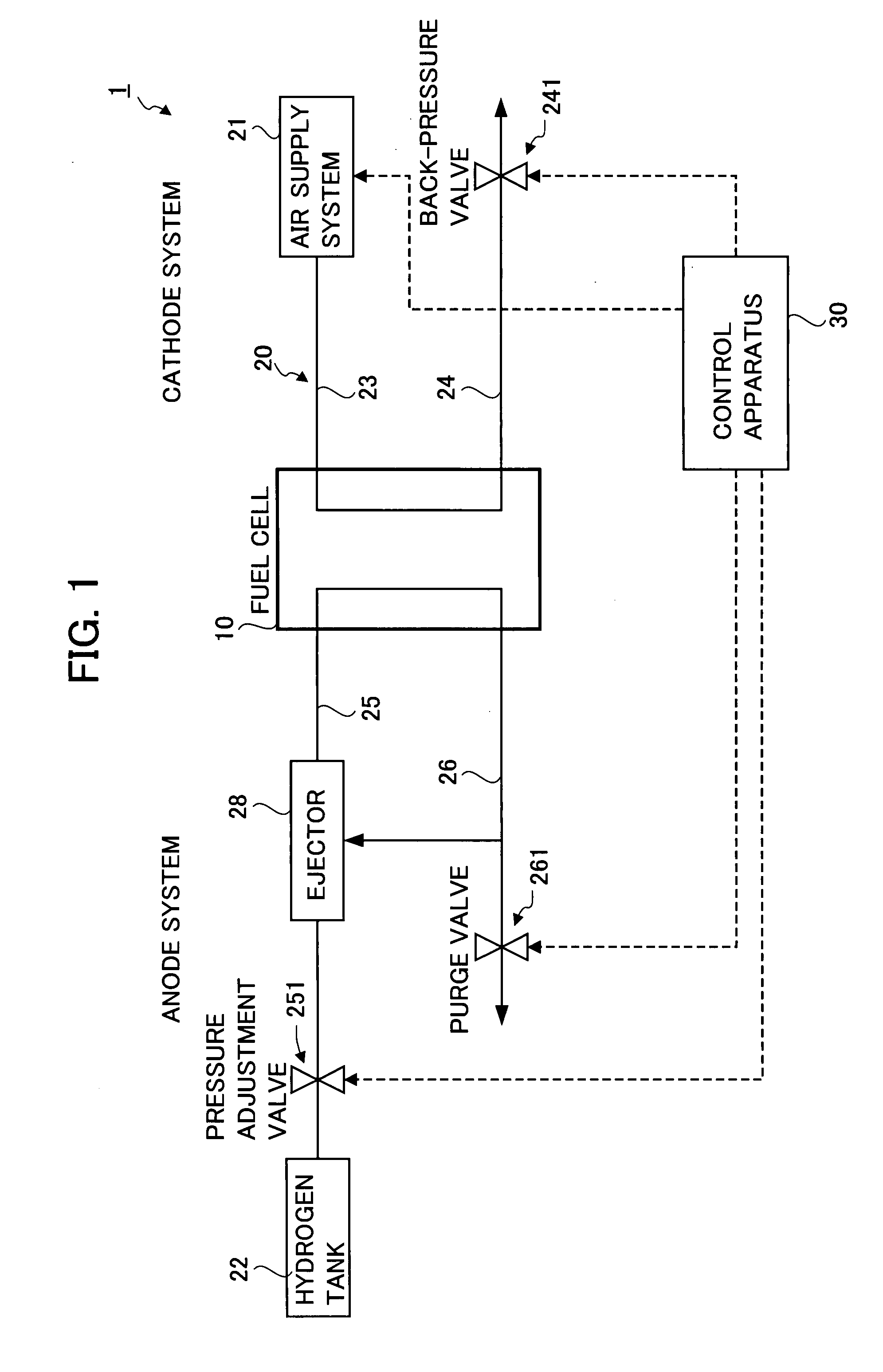
[0029]FIG. 1 illustrates a block diagram of a fuel cell system 1 using an air supply system 21.

[0030] The fuel cell system 1 has a fuel cell 10, a supply apparatus 20 which supplies hydrogen gas and air to the fuel cell 10, and a control apparatus 30 which controls the fuel cell 10 and the supply apparatus 20.

[0031] In the fuel cell 10 as described above, when the anode (positive electrode) is supplied with hydrogen gas and the cathode (negative electrode) is supplied with air containing oxygen, power is generated by way of the electrochemical reaction.

[0032] The supply apparatus 20 is configured to include an air supply system 21 which supplies air to the cathode of the fuel cell 10, and a hydrogen tank 22 and an ejector 28 which supply hydrogen gas to the anode.

[0033] The air supply system 21 is connected to the cathode of the fuel cell 10 via an air supply path 23.

[0034] The cathode of the fuel cell 10 is connected with an air exhaust path 24. The end of this air exhaust pat...

embodiment 1

Illustrative Embodiment 1

[0054]FIG. 4 shows the first illustrative embodiment and a comparative example of the air supply system. More specifically, FIG. 4 shows a relation between noise level and a compressor revolution speed when the discharge outlet of a compressor includes the rectification apparatus.

[0055] As can be seen from FIG. 4, an air supply system including the rectification apparatus can reduce noise in a wide range of revolution speeds more than in a case of the air supply system not including the rectification apparatus.

[0056] Especially, noise is greatly reduced at medium and high revolution speeds.

[0057] This embodiment provides the following advantages.

[0058] 1. The rectification apparatus 45 for rectifying air is disposed at the intake flow path 43 and the discharge flow path 44. Therefore, the turbulence associated with a shock wave caused by air intake and discharge is rectified and the sudden change of the air flow is suppressed so as to reduce the noise le...

second embodiment

[0060] The second embodiment differs from the first embodiment in the position and shape of the rectification apparatuses 45A and 45B.

[0061] More specifically, as shown in FIG. 5, a rectification apparatus 45A in an air supply system 21A is abutted with the discharge outlet of the compressor 41 and a rectification apparatus 45B is abutted with the inlet of the compressor 41.

[0062] It is assumed that the number of rectification channels 451 of the rectification apparatuses 45A and 45B to the cross-sectional area of the discharge flow path 44 and the intake flow path 43 represent a density of the rectification apparatus. It is also assumed that the lengths of the rectification apparatuses 45A and 45B in the direction along which the discharge flow path 44 and the intake flow path 43 extend represent a length of the rectification apparatus.

[0063]FIG. 6 shows a relation between the volume of air discharged from the compressor and the pressure drop by the rectification apparatus. In F...


PUM


Abstract

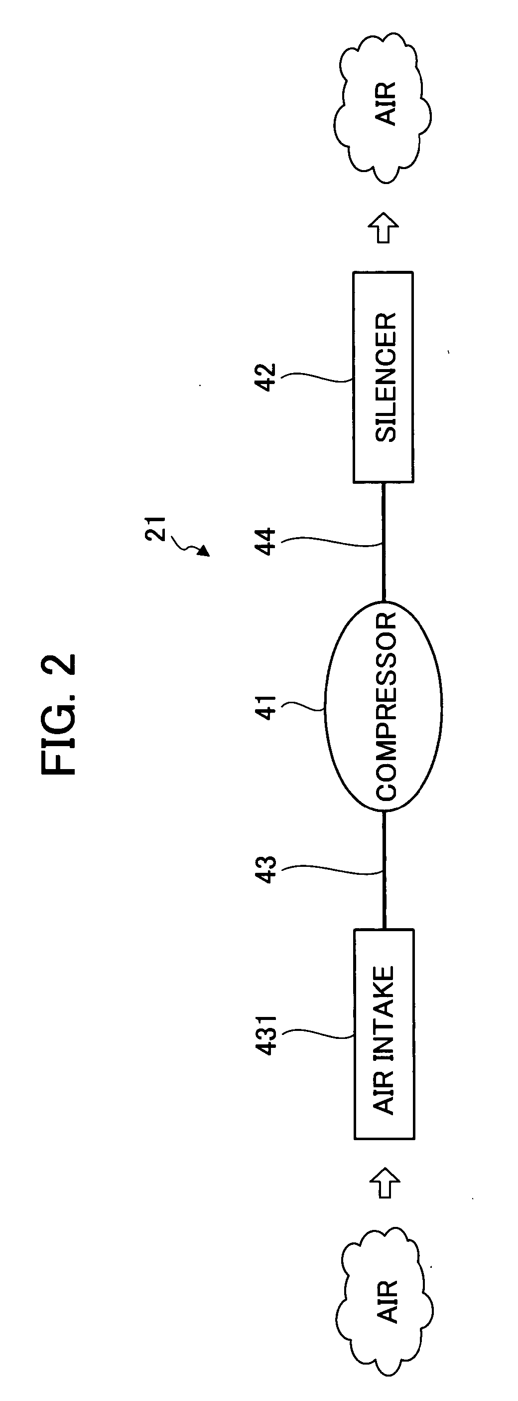
An air supply system is provided that can reduce noise of a compressor and over a wider frequency band, along with the space and cost. The air supply system includes a compressor that draws in gas to discharge the drawn in gas at an increased pressure, an intake flow path 43 in which the gas drawn in by the compressor flows, a discharge flow path 44 in which the gas discharged from the compressor 41 flows, and rectification apparatuses 45A and 45B that are disposed in the vicinity of the compressor 41 in the intake flow path 43 and the discharge flow path 44, respectively, and that rectify gas flowing therein.

Description

[0001] This application is based on and claims the benefit of priority from Japanese Patent Application No. 2006-108339 Filed on Apr. 11, 2006, and Japanese Patent Application No. 2007-102458, filed on Apr. 10, 2007 the content of which is incorporated herein by reference. BACKGROUND OF THE INVENTION [0002] 1. Field of the Invention [0003] The present invention relates to an air supply system. [0004] 2. Related Art [0005] Recently, fuel cell systems have attracted attentions as a new power source for automobiles. A fuel cell system includes, for example, a fuel cell for generating power by a chemical reaction of the reaction gas, a reaction gas supply apparatus for supplying reaction gas to the fuel cell via a reaction gas flow path, and a control apparatus for controlling the reaction gas supply apparatus. [0006] A fuel cell has a stacked structure in which, for example, a few dozen or several hundred cells are layered. In this structure, each cell is composed of a pair of separato...

Claims


Application Information

Patent Timeline
Patent Type & Authority Applications(United States)
IPC IPC(8): F04B39/00
CPCF04B39/0055Y02E60/50H01M8/04231H01M8/04089
Inventor KASUYA, KURISUGAWARA, YOSHIHIROTAJIMA, TETSUYAMATSUMOTO, KOJI
Owner HONDA MOTOR CO LTD
Learn More