Brain Cooling Device for Craniotomy Patient Having Drainage Function

a brain cooling and craniotomy technology, which is applied in the direction of surgical instruments for cooling, contraceptives, therapeutic cooling, etc., can solve the problems of difficult direct reduction of head temperature, local reduction of brain temperature using operation site rather than whole body, etc., and achieves easy removal and decrease of brain temperature.

Inactive Publication Date: 2015-01-15
KYUNGPOOK NAT UNIV IND ACADEMIC COOP FOUND
View PDF7 Cites 3 Cited by
  • Summary
  • Abstract
  • Description
  • Claims
  • Application Information

AI Technical Summary

Benefits of technology

The present invention provides a cooling system for use during craniotomy operations that can lower the temperature of the brain while also being easy to remove at the end of the procedure without requiring further surgery.

Problems solved by technology

The technical problem addressed by this patent is how to effectively lower the temperature of the brain without causing complications during surgery or other medical procedures that could lead to increased risk for patients.

Method used


Image

  • Brain Cooling Device for Craniotomy Patient Having Drainage Function
  • Brain Cooling Device for Craniotomy Patient Having Drainage Function
  • Brain Cooling Device for Craniotomy Patient Having Drainage Function

Examples


Embodiment Construction

[0020]Hereinafter, a brain cooling device for a craniotomy patient having a drainage function (hereinafter referred to as a “brain cooling device”) according to the present invention will be described in detail with reference to the accompanying drawings.

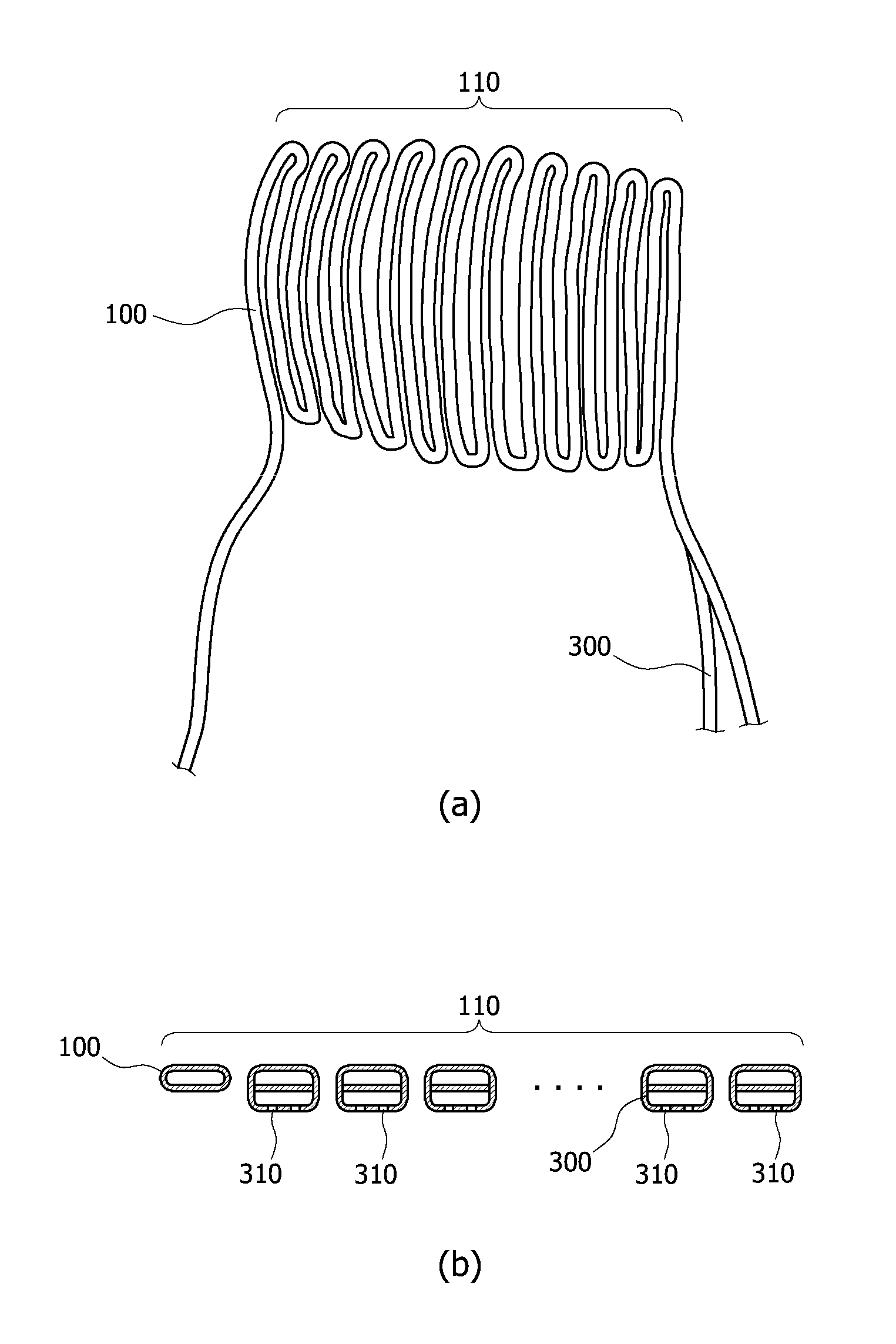
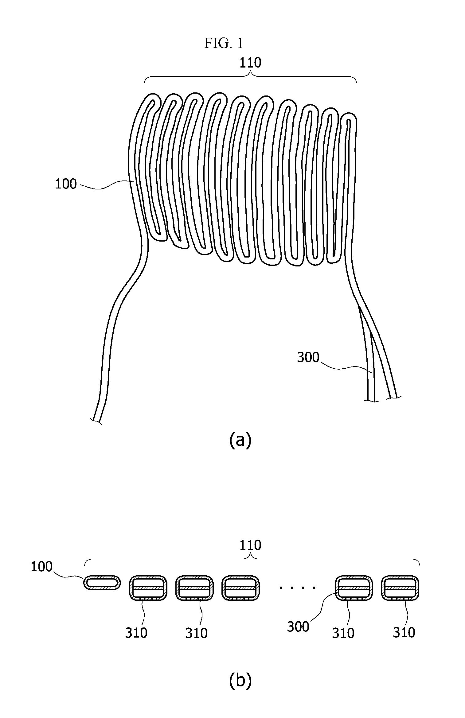
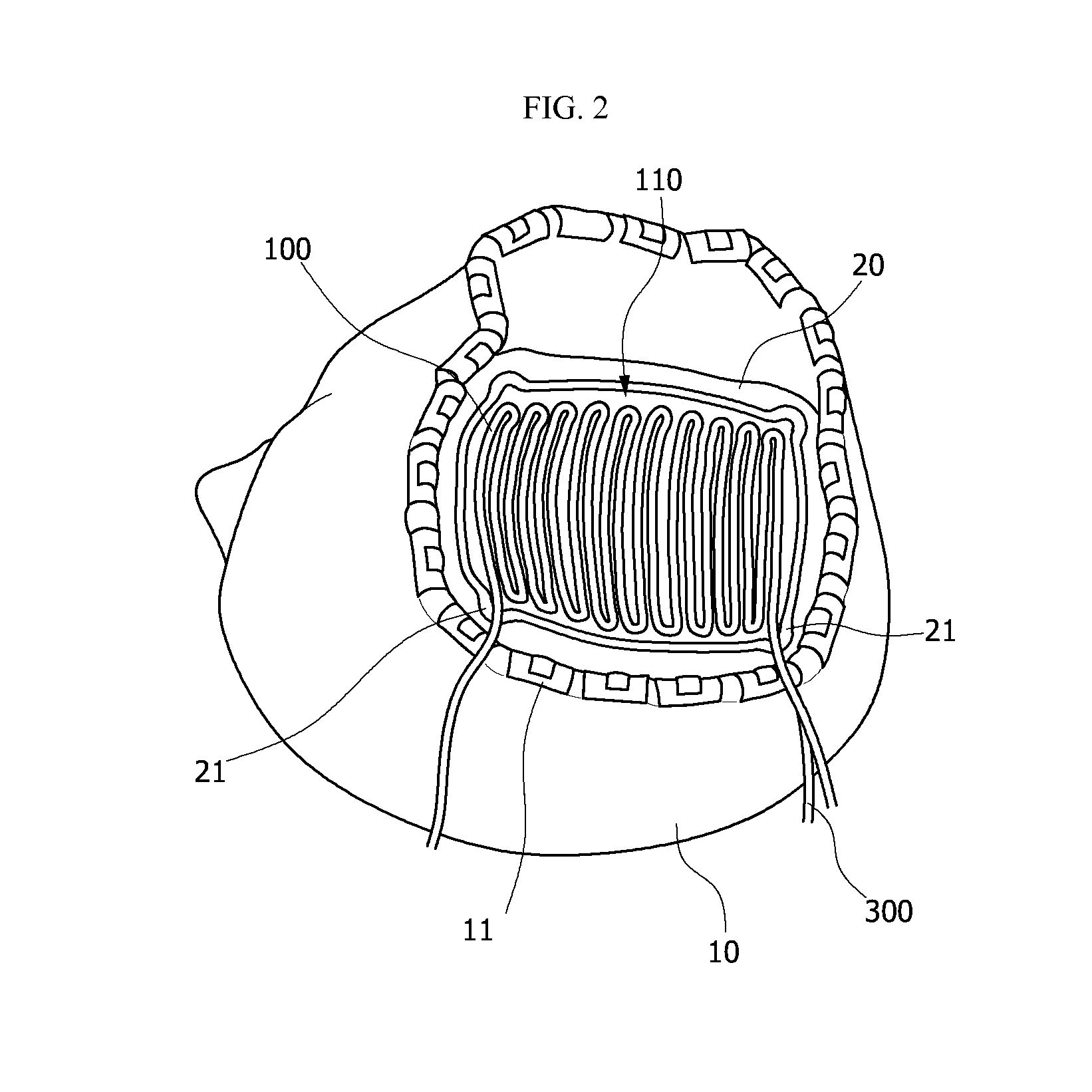
[0021]FIG. 1 is a plan view and a cross sectional view of a brain cooling device for a craniotomy patient having a drainage function according to an embodiment of the present invention. FIG. 2 is a conceptual diagram illustrating an installation state of the brain cooling device for a craniotomy patient having a drainage function illustrated in FIG. 1. FIGS. 3 and 4 are conceptual diagrams illustrating a state in which the brain cooling device for a craniotomy patient having a drainage function illustrated in FIG. 1 is installed and then suturing is performed.

[0022]As illustrated in FIG. 1, the brain cooling device according to the present invention is a cooling device installed in a brain or a dura mater and configured to cool the ...


PUM


Abstract

In a brain cooling device according to an embodiment of the present invention, preferably, temperature sensors are installed in one end and the other end of a cooling fluid transport tube to detect a temperature, a pressure measurement sensor is installed in a storage tank, a control unit is connected to the temperature sensors and the pressure measurement sensor, and the control unit calculates an amount of heat absorbed from a brain according to a change in pressure of the storage tank and the temperature detected by the temperature sensors. In the brain cooling device according to the embodiment of the present invention, preferably, one end of the cooling fluid transport tube and a drainage tube is bent such that adjacent drainage tubes come in close contact with each other. The brain cooling device according to the present invention is directly installed in a dura mater of a brain or a site in which an operation of incising the dura mater of the brain is performed so that heat or swelling is effectively mitigated. After use of the device ends, the brain cooling device may be removed through an operation hole which allows a cooling fluid to be introduced and discharged and penetrates a scalp and a cranium and thereby the device may be removed without a separate operation. When vaporized liquid nitrogen and the like are used as the cooling fluid, it is possible to cool the brain without separate mechanical and electric devices. In addition, blood and the like accumulated in an operation area may be discharged using a drain hole installed in the cooling device.

Description


Claims


Application Information

Patent Timeline
Owner KYUNGPOOK NAT UNIV IND ACADEMIC COOP FOUND
Why Eureka
Try Eureka