Imaging lens and spacer adapted to imaging lens

a technology of imaging lens and spacer, which is applied in the field of imaging lens, can solve problems such as ghosting phenomena and blurring, and achieve the effect of improving anti-reflection ability

Inactive Publication Date: 2015-01-22
GENIUS ELECTRONICS OPTICAL CO LTD
View PDF2 Cites 23 Cited by
  • Summary
  • Abstract
  • Description
  • Claims
  • Application Information

AI Technical Summary

Benefits of technology

[0007]According to another embodiment of the invention, a spacer adapted to an imaging lens comprises an inside layer and two outside layers. The inside layer is ring-shaped. The two outside layers are ring-shaped and attached on opposite sides of the inside layer, respectively. The spacer has an object-side surface, an image-side surface and a first inner ring-shaped oblique surface. The object-side surface and the image-side surface are formed outside the two outside layers in parallel and oriented toward an object side and an image side of the lens elements, respectively. The first inner ring-shaped oblique surface is formed at an inner periphery of the spacer and connected to at least one of the object-side surface and the image-side surface. An anti-reflection capability of each outside layer is better than an anti-reflection capability of the inside layer.
[0008]As mentioned in the above, the invention attaches two outside layers with better anti-reflection capability on opposite sides of the inside layer, respectively, so as to form a three-layer spacer, and forms the inner ring-shaped oblique surface at the inner periphery of the three-layer spacer. When light emitted or reflected by an object, which is located at the object side of the imaging lens, enters the lens barrel, the two outside layers and the inner ring-shaped oblique surface can restrain the light from being reflected by the inner periphery of the spacer effectively, so as to avoid the occurrence of flare or ghost phenomenon.

Problems solved by technology

However, since the spacer has a specific thickness, stray light may be reflected by an inner periphery of the spacer and then received by the imaging plane, such that flare or ghost phenomenon may occur.

Method used


Image

  • Imaging lens and spacer adapted to imaging lens
  • Imaging lens and spacer adapted to imaging lens
  • Imaging lens and spacer adapted to imaging lens

Examples


first embodiment

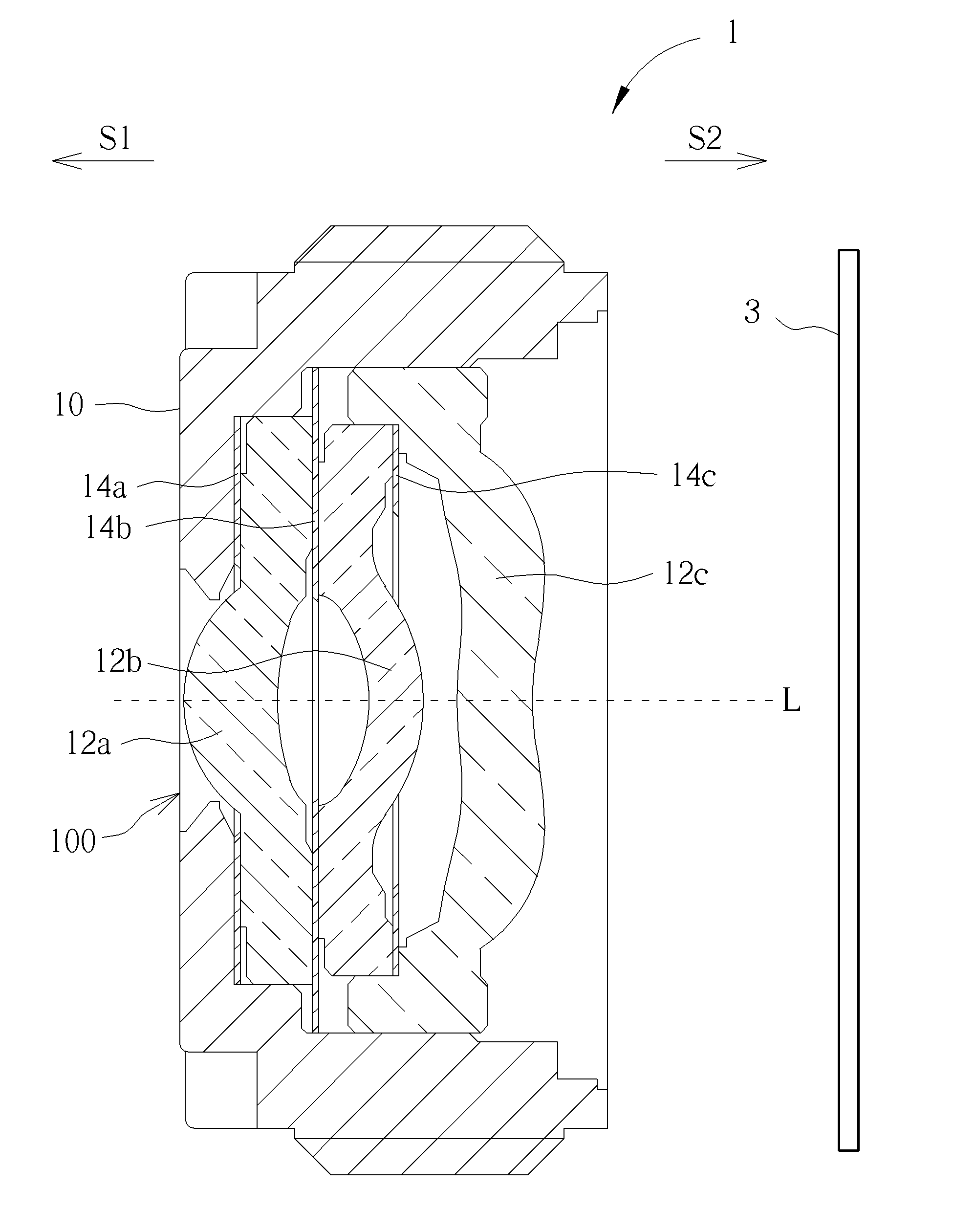
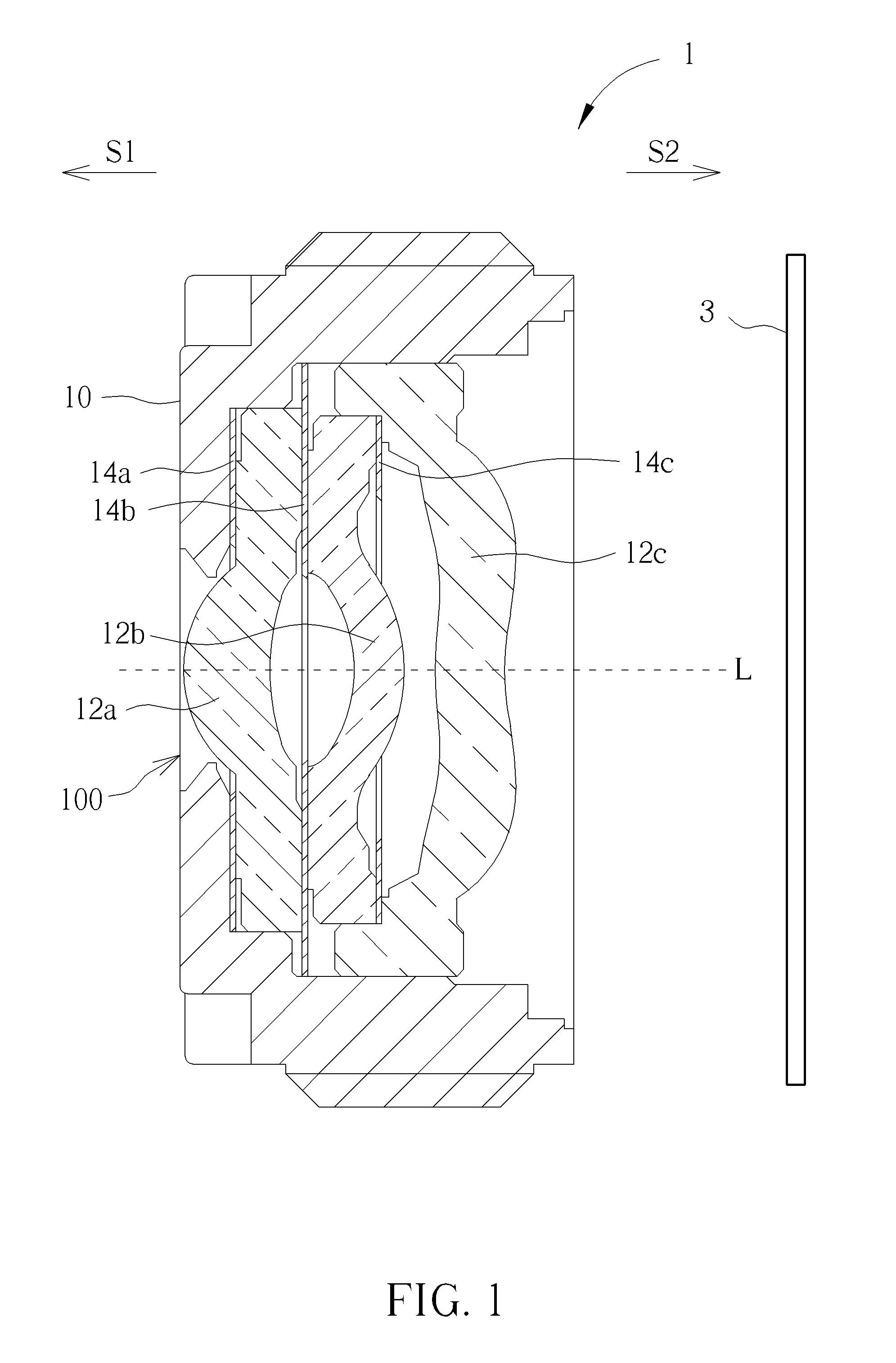
[0017]Referring to FIG. 1, FIG. 1 is a cross-sectional view illustrating an imaging lens 1 according to the invention. As shown in FIG. 1, the imaging lens 1 comprises a lens barrel 10, a plurality of lens elements 12a, 12b, 12c and a plurality of spacers 14a, 14b, 14c. In this embodiment, the imaging lens 1 comprises three lens elements 12a, 12b, 12c and three spacers 14a, 14b, 14c. The lens elements 12a, 12b, 12c and the spacers 14a, 14b, 14c all are disposed in the lens barrel 10. The lens barrel 10 has a light incident hole 100 formed at an object side S1. The spacers 14a, 14b, 14c all are ring-shaped, wherein the spacer 14a is disposed between an inner wall of the light incident hole 100 of the lens barrel 10 and the lens element 12a, the spacer 14b is disposed between two adjacent lens elements 12a, 12b, and the spacer 14c is disposed between two adjacent lens elements 12b, 12c. In other words, the spacer of the invention may be disposed between the lens barrel 10 and one of t...

third embodiment

[0023]Referring to FIG. 4, FIG. 4 is a cross-sectional view illustrating a spacer 34a according to the invention. The main difference between the spacer 34a and the aforesaid spacer 14a is that the spacer 34a further has a second inner ring-shaped oblique surface 152. As shown in FIG. 4, the first inner ring-shaped oblique surface 150 and the second inner ring-shaped oblique surface 152 both are formed at the inner periphery of the spacer 34a, and an inclined direction of the first inner ring-shaped oblique surface 150 is opposite to an inclined direction of the second inner ring-shaped oblique surface 152. In this embodiment, the first inner ring-shaped oblique surface 150 is connected between the object-side surface 146 and the second inner ring-shaped oblique surface 152, and the second inner ring-shaped oblique surface 152 is connected between the image-side surface 148 and the first inner ring-shaped oblique surface 150. The spacer 34a can eliminate a stray light from the objec...

fourth embodiment

[0024]Referring to FIG. 5, FIG. 5 is a cross-sectional view illustrating a spacer 44a according to the invention. The main difference between the spacer 44a and the aforesaid spacer 34a is that the spacer 44a further has an inner ring-shaped flat surface 154. As shown in FIG. 5, the first inner ring-shaped oblique surface 150, the second inner ring-shaped oblique surface 152 and the inner ring-shaped flat surface 154 all are formed at the inner periphery of the spacer 44a, the inner ring-shaped flat surface 154 is connected between the first inner ring-shaped oblique surface 150 and the second inner ring-shaped oblique surface 152, and the inner ring-shaped flat surface 154 is perpendicular to the object-side surface 146 and the image-side surface 148. In this embodiment, when forming the first inner ring-shaped oblique surface 150 and the second inner ring-shaped oblique surface 152 by the stamping process, the spacer 44a may be stamped by a stamping head in front of the inner ring...


PUM

PropertyMeasurementUnit
optical densityaaaaaaaaaa
thicknessaaaaaaaaaa
thicknessaaaaaaaaaa

Abstract

An imaging lens includes a lens barrel, a plurality of lens elements and a spacer. The lens elements are disposed in the lens barrel. The spacer is disposed between the lens barrel and one of the lens elements or between two adjacent lens elements. The spacer is ring-shaped and includes an inside layer and two outside layers. The two outside layers are attached on opposite sides of the inside layer, respectively. The spacer has an object-side surface, an image-side surface and a first inner ring-shaped oblique surface. The object-side surface and the image-side surface are formed outside the two outside layers in parallel and oriented toward an object side and an image side of the lens elements, respectively. The first inner ring-shaped oblique surface is formed at an inner periphery of the spacer and connected to at least one of the object-side surface and the image-side surface.

Description

BACKGROUND OF THE INVENTION[0001]1. Field of the Invention[0002]The invention relates to an imaging lens and, more particularly, to a spacer adapted to an imaging lens.[0003]2. Description of the Prior Art[0004]An imaging is a quite important optical component in a mobile electronic device or a camera and the optical property of the imaging lens determines the quality of an image. In general, the imaging lens essentially comprises a lens barrel, a plurality of lens elements and a plurality of spacers. The lens elements are disposed in the lens barrel. The spacer may be disposed between the lens barrel and one of the lens elements or between two adjacent lens elements. When light emitted or reflected by an object, which is located at an object side of the imaging lens, enters the lens barrel, it forms an image on an imaging plane at an image side of the imaging lens after passing through the lens elements. However, since the spacer has a specific thickness, stray light may be reflect...

Claims


Application Information

Patent Timeline
Patent Type & Authority Applications(United States)
IPC IPC(8): G02B7/02G02B27/00
CPCG02B7/026G02B27/0018G02B7/021G02B1/04G02B1/11G02B13/0035G02B1/113G02B13/001
Inventor CHO, HUNG-CHANGDENG, YIMANFU, WEIWEIZHAN, HAIBINXU, ZHIHONG
Owner GENIUS ELECTRONICS OPTICAL CO LTD
Why Eureka
Try Eureka