Thick tread for civil engineering tires

a technology for civil engineering tires and treads, which is applied in the direction of heavy duty tyres, vehicle components, non-skid devices, etc., can solve the problems of reduced active edge length, reduced available groove volume, and infiltration of water, and achieve the effect of limiting the undesirable effects of distance differences

Active Publication Date: 2015-01-29
MICHELIN & CO CIE GEN DES ESTAB MICHELIN
View PDF6 Cites 1 Cited by
  • Summary
  • Abstract
  • Description
  • Claims
  • Application Information

AI Technical Summary

Benefits of technology

[0013]The object of embodiments of the invention is to propose a solution to the problem outlined above, namely that of providing a tread pattern for a civil engineering vehicle tire requiring a large thickness of wearable material (that is to say, having grooves with a depth of at least 25 mm) while creating long active edges in the new state, these edges being orientated both circumferentially and transversely, and while limiting the undesirable effects of the differences in distances travelled in the contact patch between the different circumferential rows.

Problems solved by technology

These movements, which increase with the height of the blocks, may give rise to rapid localized wear as well as cracking of the rubber on the bottoms of grooves, which may then lead to infiltrations of water as far as the inner reinforcements of the tire.
A drawback of the presence of these platforms is the reduction in the available groove volume, as well as the reduction in the active edge length when the tread is worn down to the level of these platforms.
This document provides no description of a variant corresponding to the invention in any way, since the area between the shoulder ribs is highly flexible because of the presence of multiple circumferential grooves, and application to thick tires (at least 25 mm in thickness) would therefore result in accelerated wear.

Method used


Image

  • Thick tread for civil engineering tires
  • Thick tread for civil engineering tires
  • Thick tread for civil engineering tires

Examples


Embodiment Construction

[0045]In the drawings accompanying this description, the same reference symbols are used to describe variants of the invention where these reference symbols signify elements which are of the same kind in respect of their structure or function.

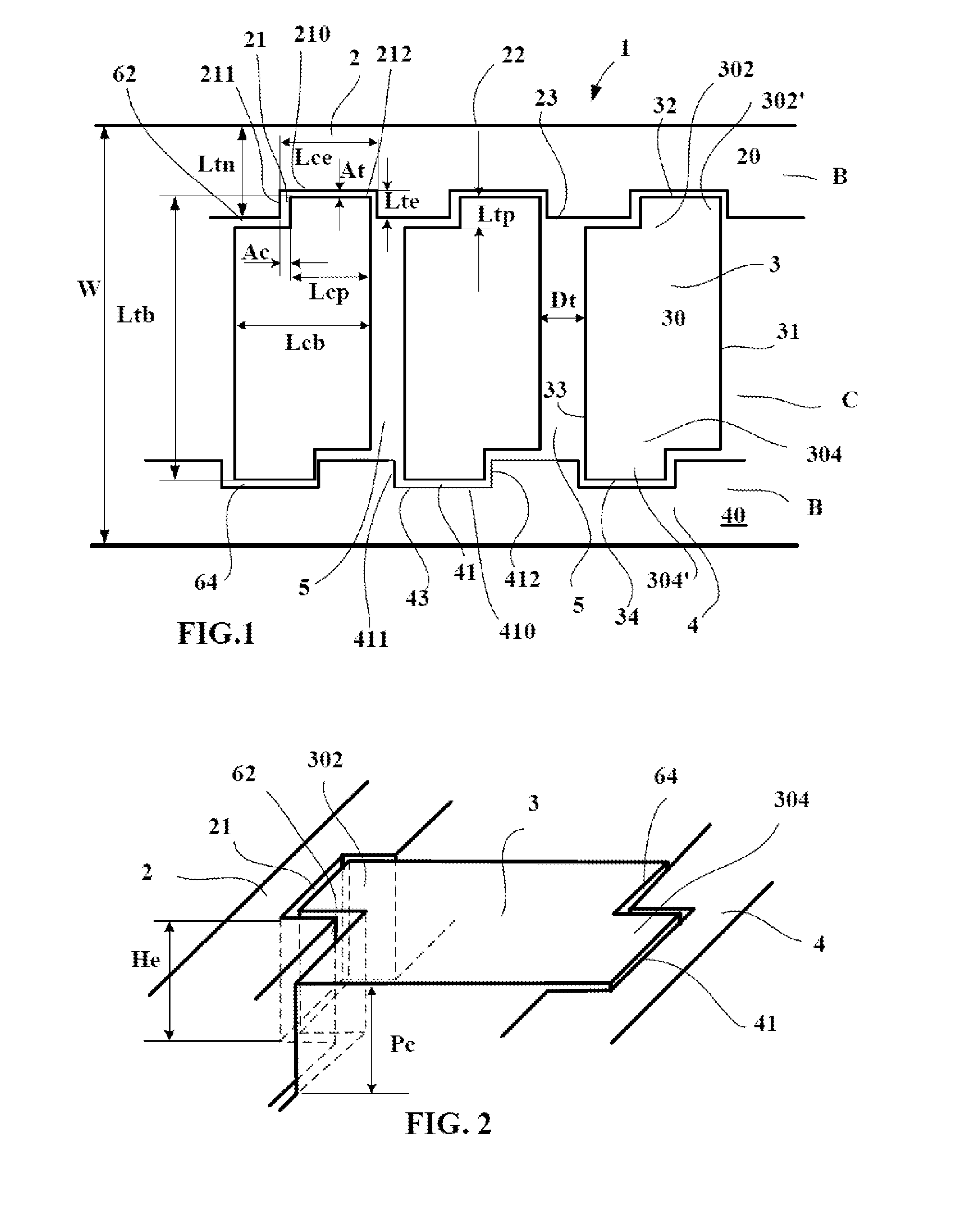
[0046]FIG. 1 shows part of a rolling surface of a tread 1 of a civil engineering tire with a size of 18.00 R 33. This tread is provided with a pattern formed by three circumferential rows, namely two edge rows B and a central row C. The tread has a total width W which is equal to 440 mm in the present case.

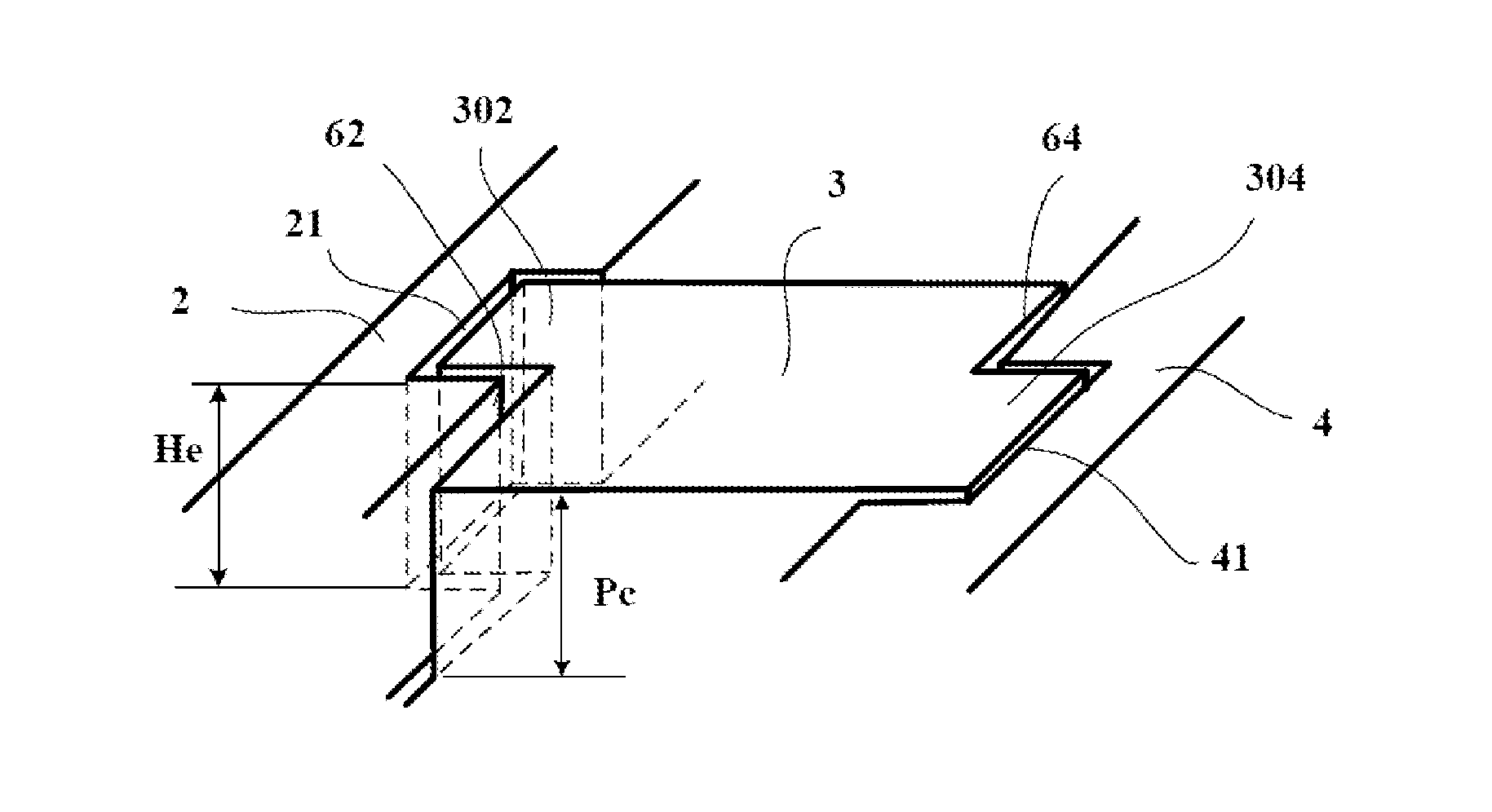
[0047]These rows B and C are separated by generally circumferentially orientated grooves 62, 64 having a depth Pc equal to 70 mm and a mean width Dc equal to 20 mm.

[0048]The central row C comprises a plurality of blocks 3 delimited from one another by transverse grooves 5 having a mean width Dt equal in the present case to 15 mm and a depth Pt equal to 70 mm.

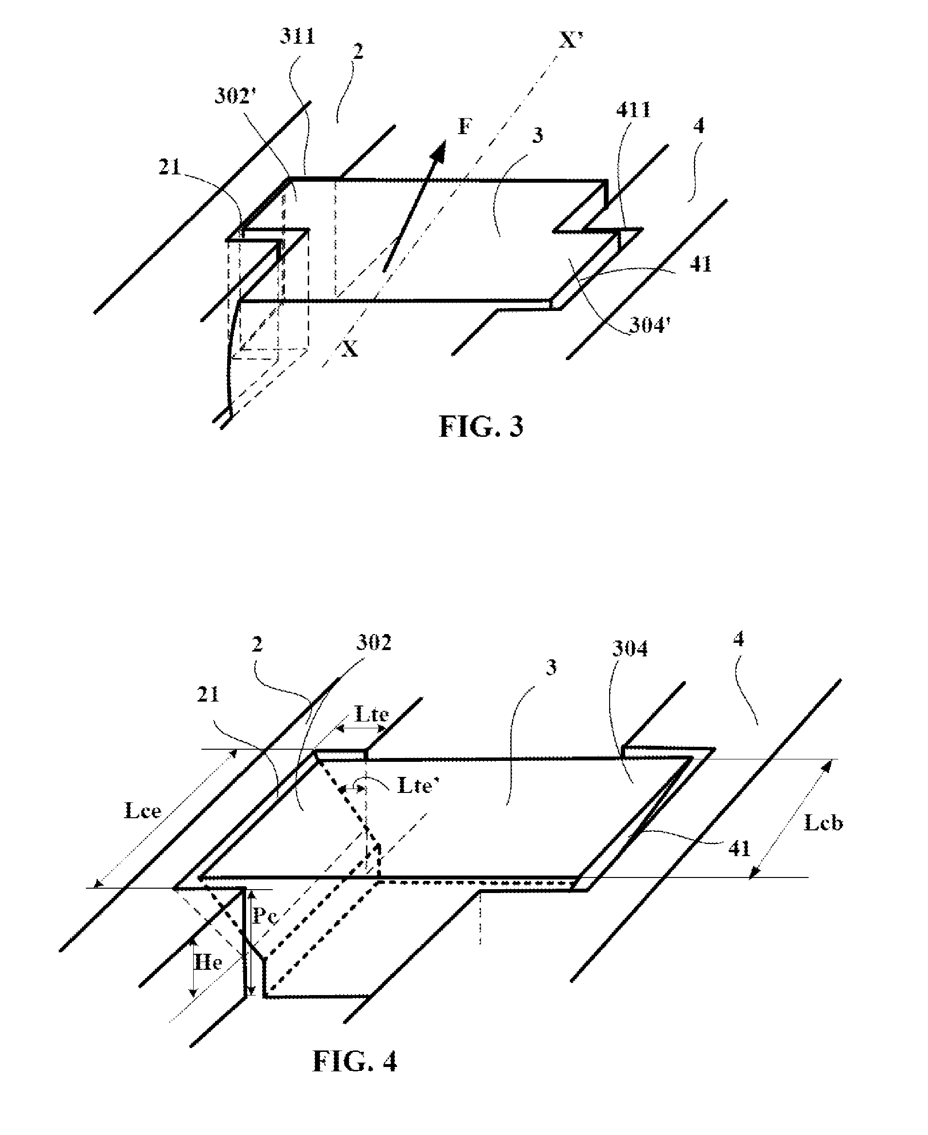
[0049]Each block 3 of the central region C comprises a contact face 30 intended to co...


PUM


Abstract

Tread for civil engineering tires, having blocks in the central part and edge ribs, each block having a width Ltb measured parallel to transverse edges and a width Lcb measured along the circumferential direction, wherein each edge rib has a plurality of recesses, forming housings, with a transverse width Lte and a circumferential length Lce, delimited over the whole of its height He by transversely orientated walls and a circumferentially orientated wall, having a suitable geometry to receive at least an end part of a block of the central region with a circumferential clearance Ac in the circumferential direction and a transverse clearance At in the transverse or axial direction, these clearances determined to ensure that, in the usual running conditions of the tire the end part of said block of the central region is at least partially in contact with at least one of the transversely orientated walls of each recess, thereby preventing each of the blocks, having its ends locked in said recesses, from coming into contact with the neighbouring blocks of the central row.

Description

[0001]This application is a 371 national phase entry of PCT / EP2013 / 053537, filed 22 Feb. 2013, which claims benefit of FR 1252368, filed 15 Mar. 2012, the entire contents of which are incorporated herein by reference for all purposes.BACKGROUND[0002]1. Field[0003]The disclosure relates to a tire for civil engineering vehicle (of the type called “off-road” in English) having a tread with a thickness of at least 25 mm. More specifically, the disclosure relates to a new type of tread having a sculpture pattern capable of limiting the differences in shear strain between the tread pattern elements that may be created, notably, by running along a curved path.[0004]These differences in shear strain may give rise to an embrittlement of the bottoms of the grooves forming the tread pattern.[0005]2. Description of Related Art[0006]A tire intended to be fitted to a civil engineering vehicle is usually provided with a tread which radially surmounts the outside of a crown reinforcement which itse...

Claims


Application Information

Patent Timeline
Patent Type & Authority Applications(United States)
IPC IPC(8): B60C11/03
CPCB60C11/0306B60C2011/0355B60C11/0309B60C11/042B60C2200/065B60C2011/133
Inventor CHAUVIN, DOMINIQUE
Owner MICHELIN & CO CIE GEN DES ESTAB MICHELIN
Why Eureka
Try Eureka