Trailer jack stand support

a technology for jack stands and jacks, which is applied in the direction of machine supports, lifting devices, transportation and packaging, etc., can solve the problems of unsatisfactory block construction, unreliable construction, and often unnecessarily high construction costs, and achieves simple assembly and or construction, and the effect of reducing the number of blocks

Inactive Publication Date: 2015-01-29
VARGAS MICHAEL
View PDF39 Cites 15 Cited by
  • Summary
  • Abstract
  • Description
  • Claims
  • Application Information

AI Technical Summary

Benefits of technology

[0007]A primary object of the present invention is to provide a new and improved jack stand for supporting stationary vehicles and other weights which is very rugged in its construction, and simple in its assembly and or construction.

Problems solved by technology

Blocks are not always acceptable because of their weight and bulk, especially when it might be advantageous to move them together with the vehicle.
Adjustable-type stands often are not stable enough to be dependable and, when constructed in a stable fashion, are frequently unnecessarily expensive.
They also have the disadvantage of not being readily stowed.
As each concrete block has a limited footprint, each block stack has a limited weight capacity with respect to the ground.
Not only is a series of concrete block stacks aesthetically unpleasant, the need to bring a large number of concrete blocks to the job sight is expensive and labor intensive.
Additionally, a relatively high concrete block stack may tend to be unstable under various loads and environmental conditions.
Such devices, although working with varying degrees of efficiency, tend to be difficult to use and maintain and are unduly heavy ad bulky.

Method used


Image

  • Trailer jack stand support
  • Trailer jack stand support
  • Trailer jack stand support

Examples


Embodiment Construction

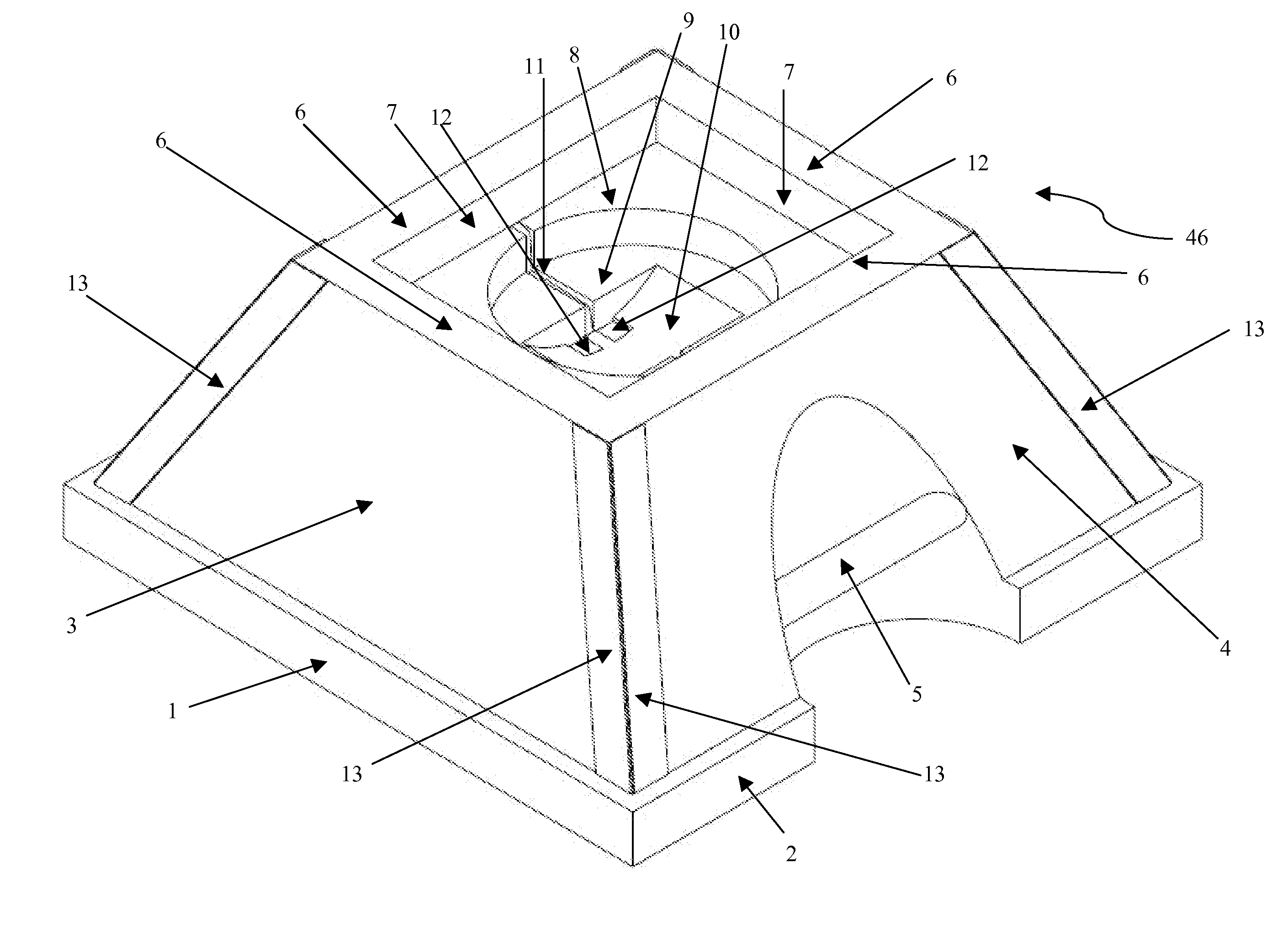
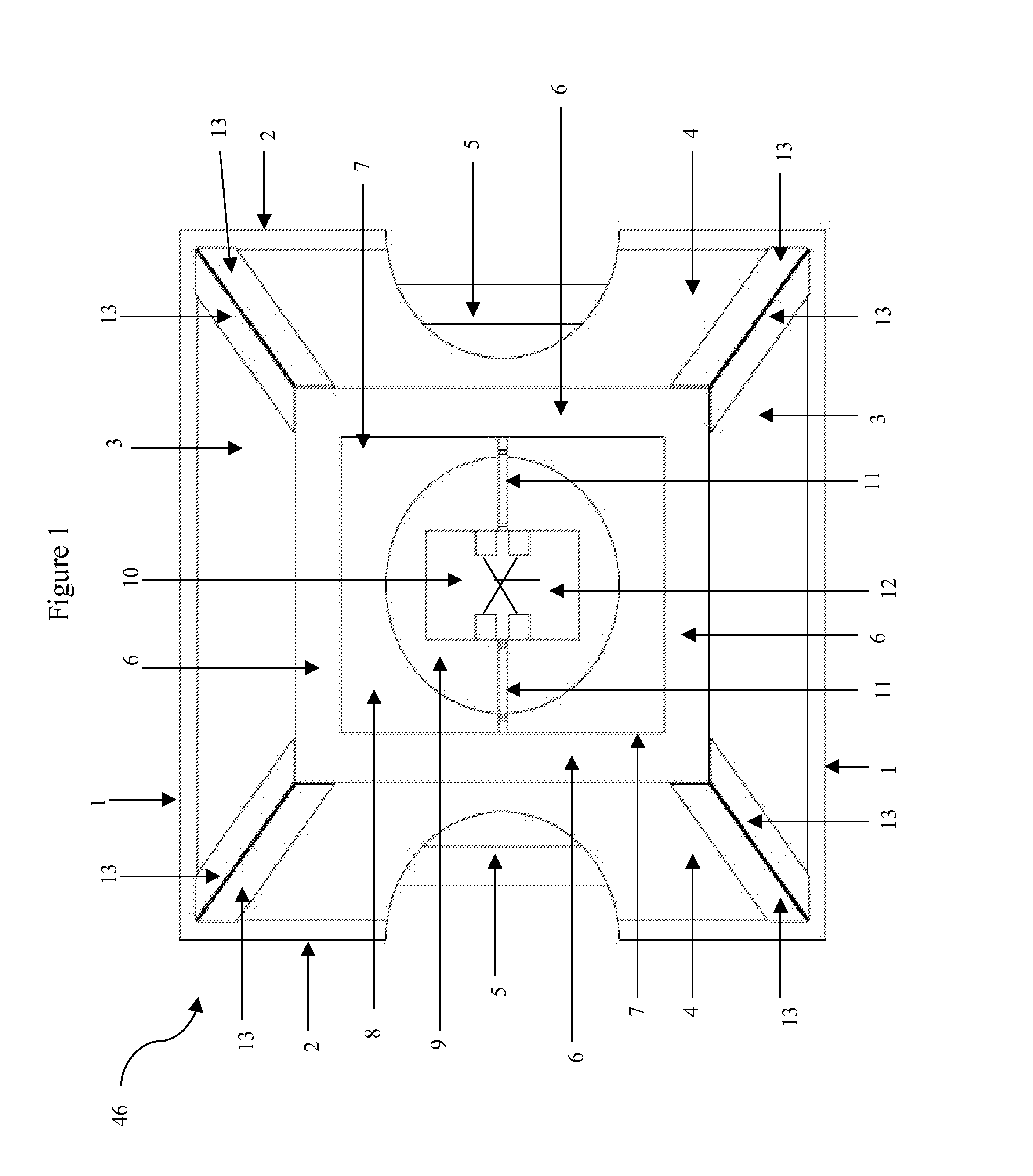
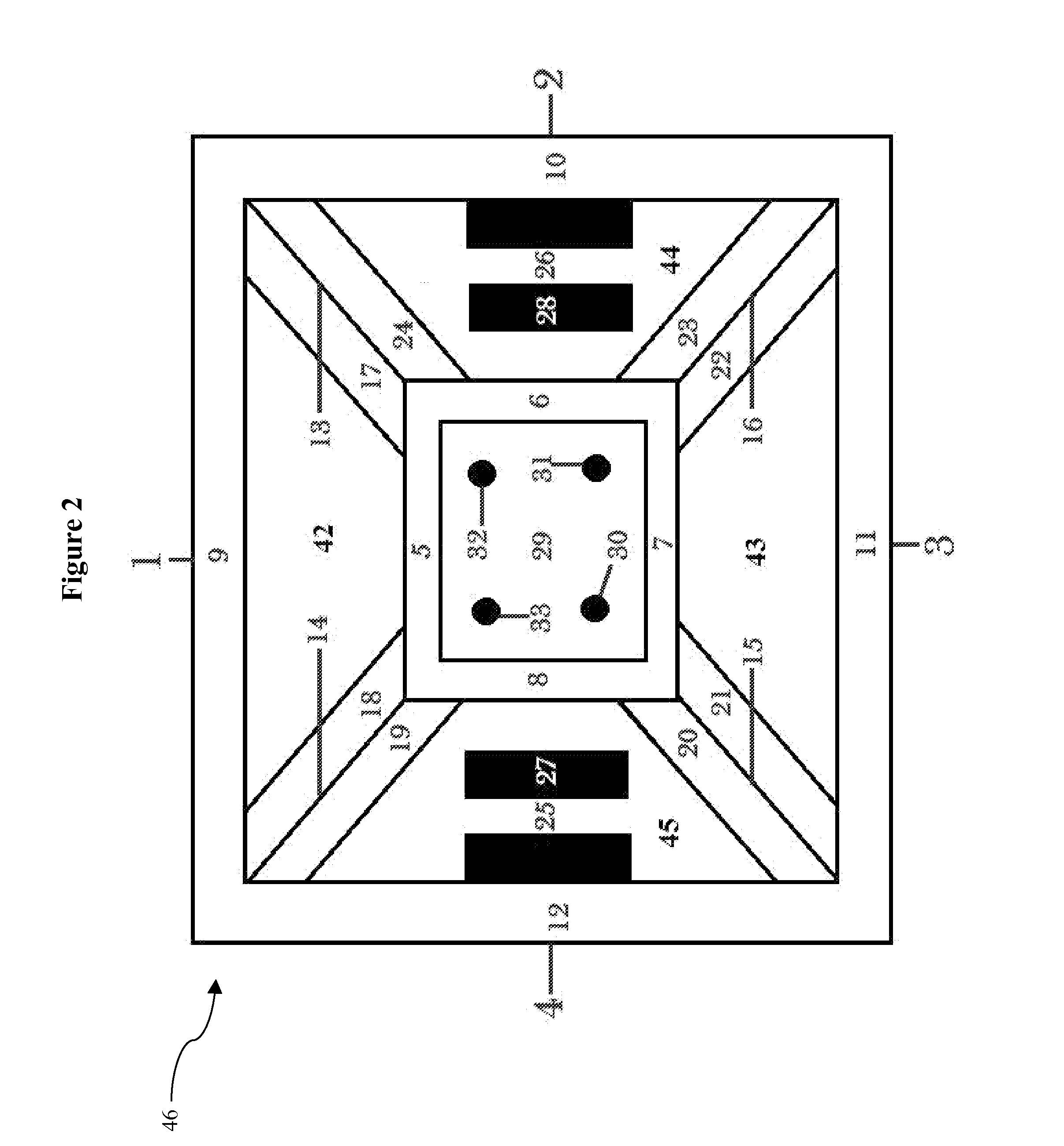
[0028]The stationary jack stand / support shown in the accompanying drawings and described below are examples which embody the invention. It should be noted that the scope of the invention is defined by the accompanying claims, and not necessarily by specific features of exemplary embodiments.

[0029]For the convenience of the reader, and with respect to FIGS. 1, 3, 5, 6, 7 and 8 the following correlation between reference numbers and elements of the invention is provided:[0030]1 represents the pyramid base support[0031]2 is the pyramid base with carved outs for handles[0032]3 pyramid base side wall[0033]4 pyramid base side wall with cut out and molded handles[0034]5 are the molded handles[0035]6 pyramid base top[0036]7 is a 3 tier jack stand support basin[0037]8 first tier is a rectangular jack stand foot support[0038]9 second tier is a circular jack stand foot support[0039]10 third tier is a wheeled jack stand foot support[0040]11 is an optional drainage channel extending through all ...


PUM


Abstract

The present invention relates to a jack stand and safety support comprising: four sides that substantially form a pyramid; two of said four sides being opposite each other including cut outs and handles; a top including a three tiers basin that includes an optional drainage channel extending across all tiers and drainage holes and glow in the dark lengthwise strips along the corners of said jack stand and support.

Description

[0001]This application claims the priority benefit under 35 U.S.C. section 119 of U.S. Provisional Patent Application No. 61 / 857,970 entitled “Trailer Jack Stand Support” filed on Jul. 24, 2013; which is in its entirety herein incorporated by reference.FIELD OF THE INVENTION[0002]The present invention relates to a device for stabilizing a trailer jack on hard or soft ground after the trailer has been disconnected from its towing vehicle, and more particularly to a stabilizing device that can receive a wheel, a jack pad or the shaft of a jack. The present invention also relates to a safety stand of substantially fixed height of such character that it can be used to support house trailers when they are parked, the drawbar end of trailers in general or, in fact, any relatively stationary and appreciably heavy weight which needs a relatively stable support.BACKGROUND OF INVENTION[0003]Various stands have been available ranging from mere blocks of wood or concrete to somewhat complicated...

Claims


Application Information

Patent Timeline
Patent Type & Authority Applications(United States)
IPC IPC(8): B66F13/00B60S9/04
CPCB60S9/04B66F13/00B60S9/02
Inventor VARGAS, MICHAEL
Owner VARGAS MICHAEL
Why Eureka
Try Eureka