Stackable merchandise trays

a technology for displaying trays and merchandise, which is applied in the field of trays for displaying merchandise, can solve the problems of easy deformation or mutilation of upstanding right-angled corners, time-consuming and labor-intensive procedures, and most containers are not suitable for displaying merchandis

Active Publication Date: 2013-01-31
MOSS GEOFFREY ALAN
View PDF11 Cites 14 Cited by
  • Summary
  • Abstract
  • Description
  • Claims
  • Application Information

AI Technical Summary

Benefits of technology

[0007]It is a principal object of the present invention to provide a tray container for the storage, transportation, as well as display purposes of merchandise without having to rearrange the merchandise at the retail location.

Problems solved by technology

However, most containers are not suitable for displaying the merchandise at the sale or retail location, since the merchandise is not readily accessible from the container by customers for selecting the items to purchase.
This procedure is time consuming and labor intensive to carry out.
However, due to the small dimensions and the unprotected upstanding right-angled corners, the upstanding right-angled corners are readily deformed or mutilated during stacking of the trays or they are destroyed by impact during moving of the stack in handling or in transportation.
When the stack of the trays is subject to accidental lateral impact it would cause the merchandise in the tray to shift due to the inherent inertia force.
As the right-angled corners are part of the extensions folded over the side walls, the pushing force would cause the securement tabs of the covering panels to disengage from the side walls of the tray, thus resulting in the loss of securement between the stacked trays.
Moreover, the folded extension portions cover over the outer surface of the side walls of the tray such that the side walls may not be provided with graphic matters for merchandising purposes.

Method used


Image

  • Stackable merchandise trays
  • Stackable merchandise trays
  • Stackable merchandise trays

Examples


Embodiment Construction

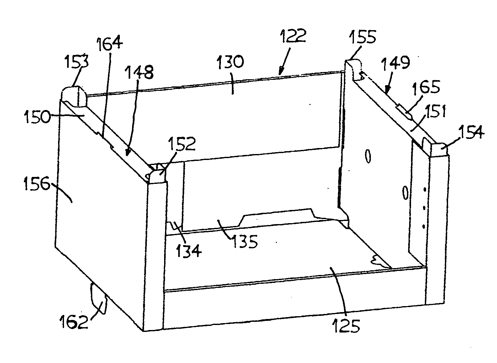
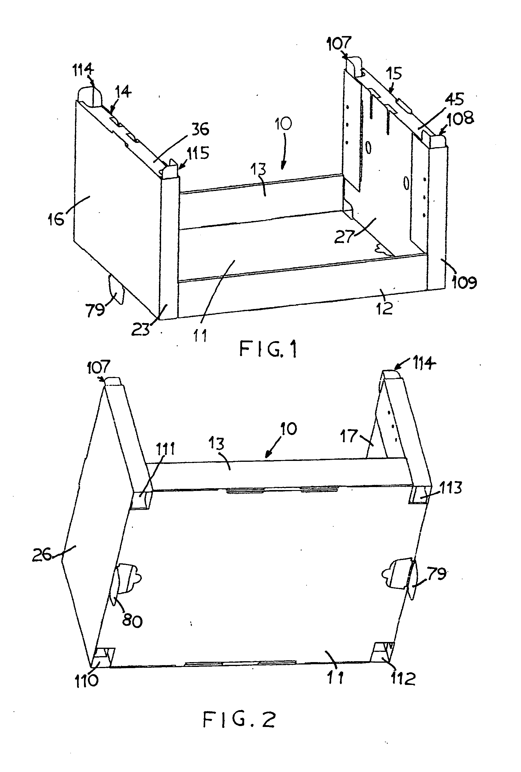
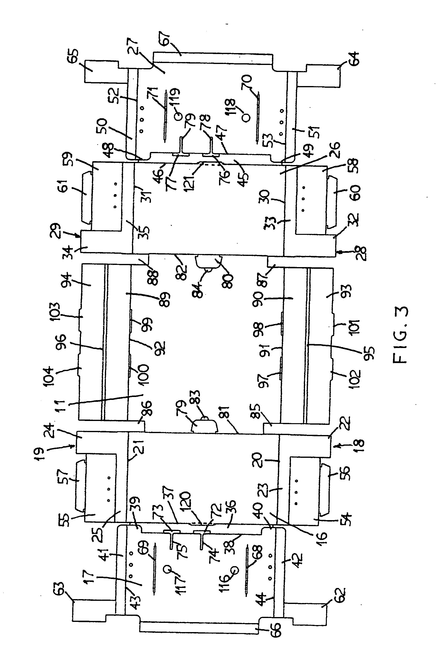
[0027]With reference to the drawings in which like reference numerals designate corresponding parts in the different views, the tray container 10 according to the present invention has a generally lateral U shape with a rectangular bottom panel 11. A rectangular front panel 12 having a low height extends upwards from the front edge of the bottom panel 11, and an equally low height rectangular rear panel 13 extends upwards from the rear edge of the bottom panel 11. The low height front and rear panels 12 and 13 facilitate easy visibility and access to and the merchandise located in the tray container from either the front or rear thereof. A generally rectangular weight supporting and reinforcement left casing 14 is located vertically upwards from the left side edge portion of the bottom panel 11, and an equal rectangular weight supporting and reinforcement right casing 15 is located vertically upwards from the right side edge portion of the bottom panel 11. The left casing 14 has a c...


PUM


Abstract

Rugged stackable merchandise tray containers are provided with right-angled mounting tabs at the inner corners of the top panel of two load supporting casing formed at the two ends of the tray container. The right-angled mounting tabs are engageable with rectangular mounting openings formed at the bottom of the bottom panel when two tray containers are stacked one on top of another. The mounting provide resistance to accidental external impact exerted to the stack. At least one trapezoidal shape pull-out tabs are also provided at the edge portion of the bottom panel, which are engageable with aligned mounting slots formed at the top panel of the load supporting casings to provide further securement of the stacked tray containers as well as enhanced resistance to external impact to the stack.

Description

BACKGROUND OF THE INVENTION[0001]1. Field of the Invention[0002]This invention relates to merchandise containers for transporting, storing and display merchandise, and particularly to tray containers which can be stacked together securely to withstand accidental external impact.[0003]2. Background Art[0004]Containers made of corrugated board or cardboard are commonly employed for transporting and for storage of merchandise. However, most containers are not suitable for displaying the merchandise at the sale or retail location, since the merchandise is not readily accessible from the container by customers for selecting the items to purchase. Accordingly, the merchandise, after transported to the sale or retail location, must be unpacked from the containers and be transferred to display shelves, stands, or show cases in order that customers may select the items to purchase. This procedure is time consuming and labor intensive to carry out.[0005]Containers can be made in the form of t...

Claims


Application Information

Patent Timeline
Patent Type & Authority Applications(United States)
IPC IPC(8): B65D21/032
CPCB65D5/0035B65D5/305B65D5/22
Inventor MOSS, GEOFFREY ALAN
Owner MOSS GEOFFREY ALAN
Why Eureka
Try Eureka