Cleaning device and method of use

a cleaning device and cleaning method technology, applied in the field of cleaning devices, can solve the problems of limited ability to release continuous streams of soap or disinfectant, environmental challenges in the use of aerosol sprays, and less durable than is desired, and achieve the effects of simple and cost effective mechanism, simple operation, and cost effective manufactur

Inactive Publication Date: 2005-09-29
BRUMLIK JOHN FRANCOIS
View PDF57 Cites 11 Cited by
  • Summary
  • Abstract
  • Description
  • Claims
  • Application Information

AI Technical Summary

Benefits of technology

[0025] g. The preferred embodiments allow different methods to deliver controllable amounts of cleaning or disinfectant solution to the scrubber head. The preferred methods operate using a simple and cost effective mechanism to open one or more otherwise sealed orifices at the base or side of the reservoir. As only one example, an orifice can be opened by a valve which is normally held closed by a plunger with an axially mounted compression spring. When desired, the plunger can be manually depressed from one or several of a variety of remote positions on the outside of the shaft of the device, thereby causing the orifice to be opened and allowing cleaning or disinfectant solution to flow from the reservoir to the scrubber head in either continuous flow or a fixed controlled amount, depending on the valve design.
[0026] Further objectives and advantages of the present invention are to provide a cleaning device that is cost effective to manufacture, simple to operate, and rugged in construction. Further objectives will become apparent from a consideration of the drawings and ensuing descriptions.

Problems solved by technology

Cleaning toilets and other bathroom and household fixtures is an inherently dirty business, not only in terms of general cleanliness, but also because these areas are typically prone to growth of bacteria and other germs.
Additionally, these separately contained disinfectants often use environmentally challenging aerosol sprays.
While these types of devices offer some help for certain household cleaning chores, they are either inadequate for cleaning jobs which require significant release of soap or fluid due to undeveloped sealing mechanics, or they have limited ability to release continuous streams of soap or disinfectant.
Given the force which is often exerted on bathroom brushes during use, the compressibility of these devices makes them less durable than is desired.
The air vent is usually in contact with the fluid as the fluid is being released from the container through the nipple means, thereby significantly reducing the efficacy of the air vent and making the design generally insufficient for most household cleaning chores.
In fact, it is actually counterproductive for cleaning devices since a common complaint of currently available dispensing cleaning brushes is that they leak.
While pumps may provide an effective delivery tool for many purposes, this high cost design makes it an inefficient alternative to the common bathroom brushes of today.
However, since this design contains no flow control mechanism, it requires that the brush head be kept higher than the reservoir while not in use, or else the liquid flows unobstructed to the brush head.
This makes the design impractical for most bathroom cleaning uses since most people store their toilet bowl and other bathroom brushes standing or hanging with the brush head below the handle.

Method used


Image

  • Cleaning device and method of use
  • Cleaning device and method of use
  • Cleaning device and method of use

Examples


Embodiment Construction

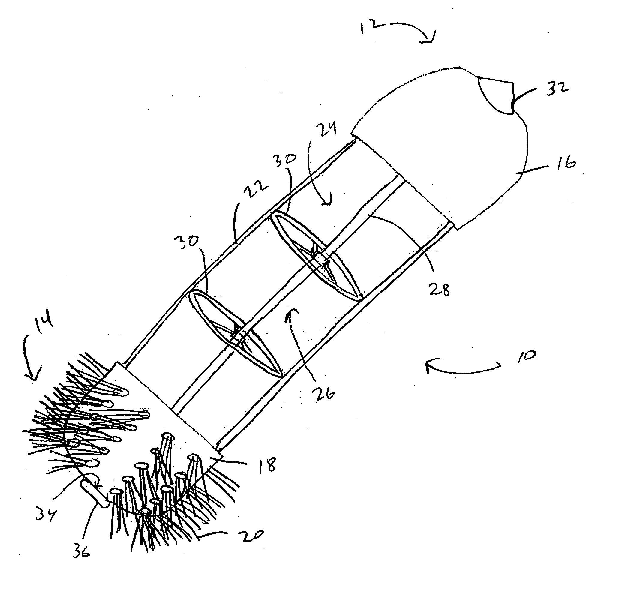
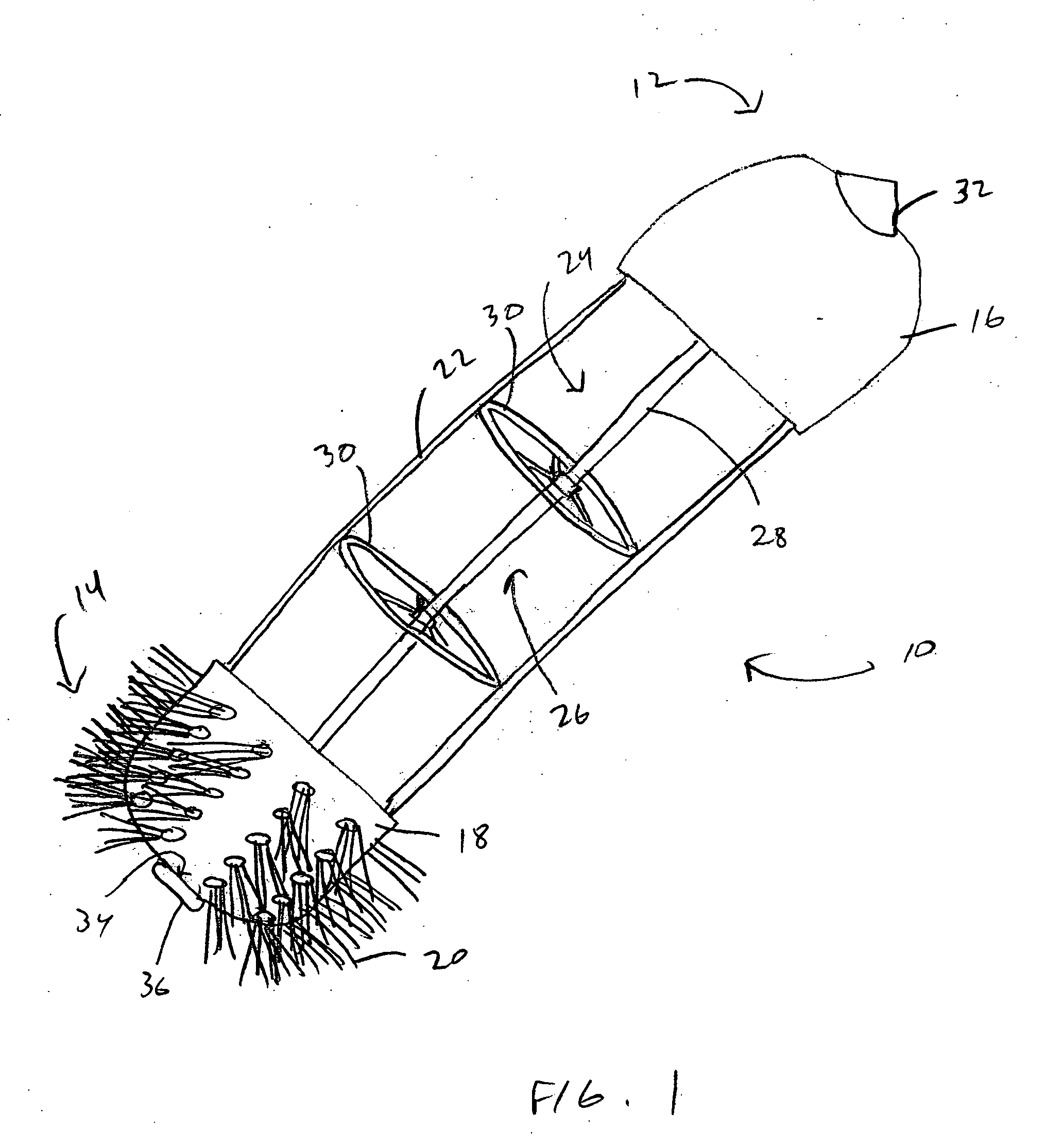
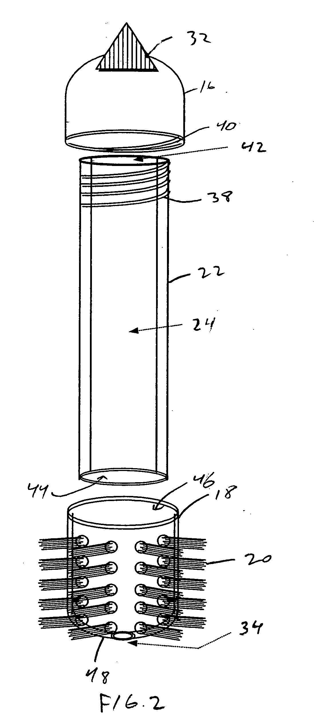
[0046] The preferred embodiments of the present invention describe a method and apparatus for dispensing cleaning solution, such as for toilet, bathroom or household use. The particular embodiments described below include a brush designed for cleaning and disinfecting toilets and urinals. However, it will be appreciated that designs for other cleaning applications, such as for cleaning and disinfecting bathroom and kitchen sinks and showers and other household and non-household areas, are also contemplated as being within the scope of this invention. Furthermore, the embodiments of the present invention may also be applied to other applications wherein it is desired to dispense a volume of solution to a surface for cleaning or other purposes.

[0047] As used herein, the terms “liquid,”“solution,”“gel,”“cleanser” and “disinfectant” are interchangeable and include, but are not limited to, materials in all phases, although preferably not in gas or non-flowable solid phase.

[0048] The te...


PUM


Abstract

A cleaning device for cleaning toilets, bathroom fixtures, and other surfaces. The device encloses a reservoir contained in a hollow handle for storing a cleaning solution, with a cap connected to one end of the handle and a base connected to the other end of the handle. A brush, sponge or other scrubber or cleaning surface is preferably attached to the base. A manually operated flow control mechanism opens a valve which seals at least one exit or dispensing orifice at or near the base of the reservoir, and thereby allows volume of cleaning solution to be dispensed at a reasonably fast, controlled rate of flow. In one embodiment, manually operated vacuum pressure release orifices are located at the opposite end of the reservoir from the exit orifice and are normally closed, but may be opened to minimize or eliminate any vacuum (subatmospheric pressure) in the reservoir, thereby aiding the flow of liquid from the reservoir through the exit orifice.

Description

CROSS-REFERENCE TO RELATED APPLICATIONS [0001] This application is a divisional of U.S. application Ser. No. 10 / 659,613, filed Sep. 10, 2003, which is a divisional of U.S. application Ser. No. 09 / 745,146, filed Dec. 20, 2000, which claims the benefit of U.S. Provisional Application No. 60 / 172,260, filed Dec. 20, 1999, and U.S. Provisional Application No. 60 / 231,217, filed Sep. 8, 2000. The entirety of these applications are hereby incorporated by reference.BACKGROUND OF THE INVENTION [0002] 1. Field of the Invention [0003] This invention relates to a cleaning device which combines a scrubbing member with a handle and a reservoir for holding cleaning or disinfectant solution. More particularly, this invention relates to a method and apparatus for dispensing such solution at or near to the scrubber in a controlled manner. [0004] 2. Description of the Related Art [0005] Cleaning toilets and other bathroom and household fixtures is an inherently dirty business, not only in terms of gene...

Claims


Application Information

Patent Timeline
Patent Type & Authority Applications(United States)
IPC IPC(8): A46B11/00A46B11/04A47K11/10B08B7/00G09F7/12
CPCA46B11/0013A46B11/0062A46B11/0079G09F7/12A46B2200/304A47K11/10A46B2200/3033
Inventor BRUMLIK, JOHN FRANCOIS
Owner BRUMLIK JOHN FRANCOIS
Why Eureka
Try Eureka