Universal Chair Lift Apparatus

a universal and chair technology, applied in the field of wheelchair lifts, can solve the problems of not being universally compatible with any chair, putting people at risk, incurring additional costs, etc., and achieve the effect of adding a lift system and preventing peopl

Inactive Publication Date: 2015-01-29
REBORSE CORA MARIE
View PDF16 Cites 10 Cited by
  • Summary
  • Abstract
  • Description
  • Claims
  • Application Information

AI Technical Summary

Benefits of technology

The present invention provides a way to make a device that can be used with different types of chairs. It also allows the user to control the lifting or lowering of the chair to their desired height. Additionally, the device doesn't tilt the chair forward when it's raised, which prevents people with medical conditions from getting hurt. This invention is a cost-effective way to add a lift system to an existing chair in your home.

Problems solved by technology

The technical problem of this patent text is to provide a more efficient and cost-effective method for producing a specific type of chemical compound.

Method used


Image

  • Universal Chair Lift Apparatus
  • Universal Chair Lift Apparatus
  • Universal Chair Lift Apparatus

Examples


Embodiment Construction

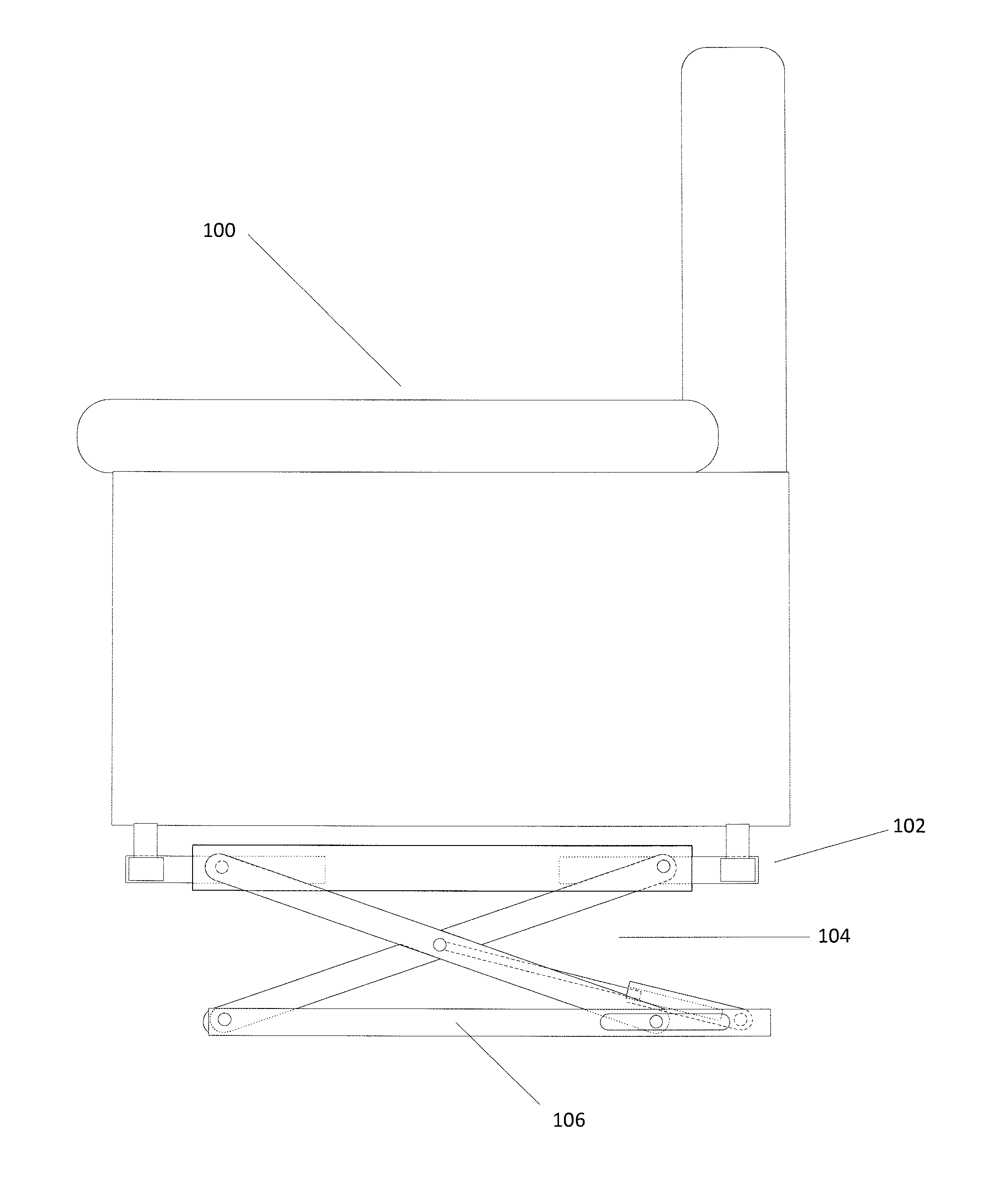
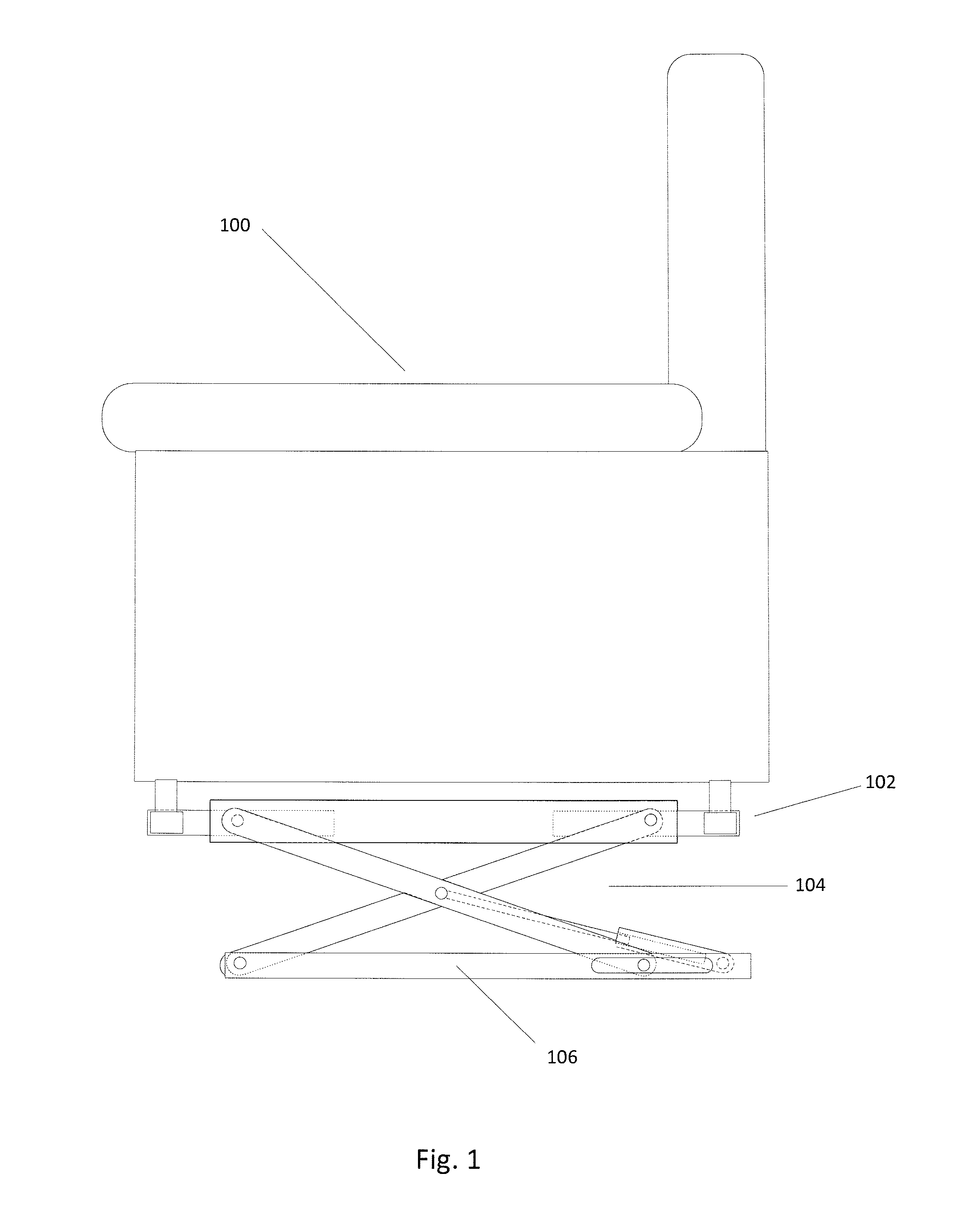
[0021]FIG. 1 illustrates a chair lifting apparatus in an operational position. A chair 100 is affixed a top a upper support 102 by a leg engagement means 214 that has been adjusted to fit the chair 100 and will be described later if further detail. The upper support 102 is pivotally affixed to the scissor lift 104. The scissor lift 104 is pivotably and slideably affixed to the base 106.

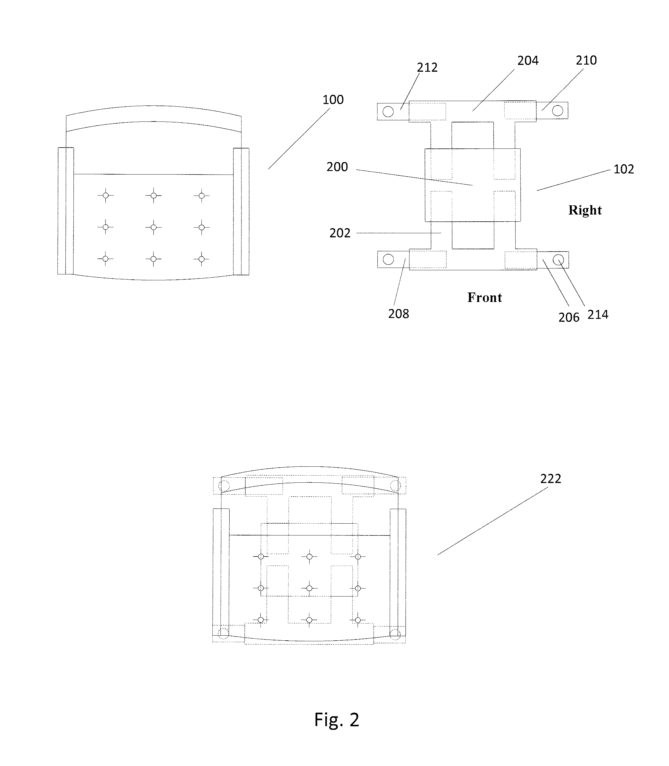
[0022]FIG. 2 illustrates a top view of the chair 100, upper support 102, and a composite top view 222 of the chair affixed a top the upper support 102. FIG. 2 further illustrates the upper support 102 with its component parts a body 200, a front longitudinal adjustment 202, a rear longitudinal adjustment 204, front left lateral adjustment 206, front right lateral adjustment 208, rear right lateral adjustment 210, rear left lateral adjustment 212, and leg engagement means 214.

[0023]The front longitudinal adjustment 202 and rear longitudinal adjustment 204 are shown received within body 200 and can be e...


PUM


Abstract

An adjustable lift apparatus for use with a rocking/reclining chair having at least one support leg, the apparatus comprising an upper support having at least one leg stand to securely engage at least one leg, and an adjustment means for adjusting each leg support stand to the desired location to engage all of the chair's legs; a lift means for reversibly biasing the upper support away from the base; a base adapted to rest on the floor and support the apparatus; a controller in communication with and controlling the lift means, whereby, the adjustable lift apparatus provides an inexpensive and universal way of engaging and raising the rocker/recliner chair with varying styles of legs and bases through the use of a controller to automatically position the chair to a user desired height thereby making it easier for elderly and handicapped persons to get into and out of the chair.

Description


Claims


Application Information

Patent Timeline
Owner REBORSE CORA MARIE
Why Eureka
Try Eureka