Rotor for rotating electric machine, rotating electric machine, and method for manufacturing rotor for rotating electric machine
a technology of rotating electric machines and rotors, which is applied in the direction of manufacturing stator/rotor bodies, rotating parts of magnetic circuits, and rotating magnetic circuits. it can solve the problems of increasing the operating time, preventing manpower saving and productivity improvement, and complicated permanent magnets and core members
- Summary
- Abstract
- Description
- Claims
- Application Information
AI Technical Summary
Benefits of technology
Problems solved by technology
Method used
Image


Examples
embodiment 1
[0095]Hereinafter, a rotor for a rotating electric machine according to embodiment 1 of the present invention will be described with reference to the drawings.
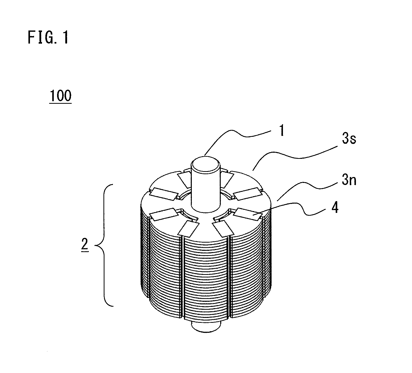
[0096]FIG. 1 is a perspective view of a rotor 100.
[0097]FIG. 2 is an exploded perspective view of the rotor 100.
[0098]FIG. 3 is a plan view of the rotor 100.
[0099]FIG. 39 is a sectional view of an electric motor 50 (rotating electric machine).
[0100]The rotor 100 for use in the electric motor 50 (rotating electric machine) shown in FIG. 39 is structured by a non-magnetic rotation shaft 1, a plurality of permanent magnets 4 (first permanent magnets) that are magnetized around the rotation shaft 1 in an alternate manner in the circumferential direction, an N pole integrally-stacked core 3n, and an S pole integrally-stacked core 3s, being combined with each other.
[0101]Hereinafter, in the description herein, although the N pole integrally-stacked core 3n and the S pole integrally-stacked core 3s are represented by individual names...
embodiment 2
[0150]Hereinafter, a rotor for a rotating electric machine according to embodiment 2 of the present invention will be described with reference to the drawings, focusing on difference from embodiment 1.
[0151]The components denoted by the same reference numerals as used in embodiment 1 basically represent the same components.
[0152]FIG. 10 is a sectional view of a rotor 200.
[0153]In the rotor 200, a non-magnetic collar 211 that is a separate member is fitted around a non-magnetic rotation shaft 201, and the rotation shaft 201 is formed as a member having the same shape as the rotation shaft 1 of embodiment 1.
[0154]In such a structure, the usage of an expensive non-magnetic material can be reduced as compared with embodiment 1.
[0155]Further, assembling process steps of sequentially fitting the N pole integrally-stacked core 3n, the non-magnetic collar 211, and the S pole integrally-stacked core 3s, to the non-magnetic rotation shaft 201 can be adopted, and operability and productivity c...
embodiment 3
[0156]Hereinafter, a rotor for a rotating electric machine according to embodiment 3 of the present invention will be described with reference to the drawings, focusing on difference from embodiment 2.
[0157]The components denoted by the same reference numerals as used in embodiment 1 or 2 basically represent the same components.
[0158]FIG. 11 is a sectional view of a rotor 300.
[0159]FIG. 12 is an enlarged view of a specific portion in FIG. 11.
[0160]In the rotor 300, a cylindrical permanent magnet 311 (second permanent magnet) is fitted around the non-magnetic rotation shaft 201, and the rotation shaft 201 and the cylindrical permanent magnet 311 have the same shape as the rotation shaft 1 of embodiment 1.
[0161]As shown in FIG. 12, the permanent magnet 311 is magnetized so as to have the N pole on a side on which the permanent magnet 311 contacts with the stacked annular connecting portion 36n of the N pole integrally-stacked core 3n, and have the S pole on a side on which the permane...
PUM
| Property | Measurement | Unit |
|---|---|---|
| shape | aaaaa | aaaaa |
| outer circumference | aaaaa | aaaaa |
| magnetic | aaaaa | aaaaa |
Abstract
Description
Claims
Application Information
 - R&D
- Intellectual Property
- Life Sciences
- Materials
- Tech Scout
- Unparalleled Data Quality
- Higher Quality Content
- 60% Fewer Hallucinations
Browse by: Latest US Patents, China's latest patents, Technical Efficacy Thesaurus, Application Domain, Technology Topic, Popular Technical Reports.
© 2025 PatSnap. All rights reserved.Legal|Privacy policy|Modern Slavery Act Transparency Statement|Sitemap|About US| Contact US: help@patsnap.com