Robotic arm

a robotic arm and arm technology, applied in the field of robots, can solve the problems of high robotic arm manufacturing cost and uneconomic use of the above-mentioned robotic arm, and achieve the effects of reducing the number of servomotors, cost reduction, and optimal moving and swinging operations

Active Publication Date: 2015-02-05
HIWIN TECH
View PDF8 Cites 20 Cited by
  • Summary
  • Abstract
  • Description
  • Claims
  • Application Information

AI Technical Summary

Benefits of technology

[0006]The present invention has been accomplished under the circumstances in view. It is the main object of the present invention to pr...

Problems solved by technology

However, in order to make complicated actions, the robotic arm needs to use multiple servomotors, resulting in a high robotic arm manufacturing cost and the indisputable fact that it is really not conducive to using a large amount of robotic ar...

Method used


Image

  • Robotic arm
  • Robotic arm
  • Robotic arm

Examples


Embodiment Construction

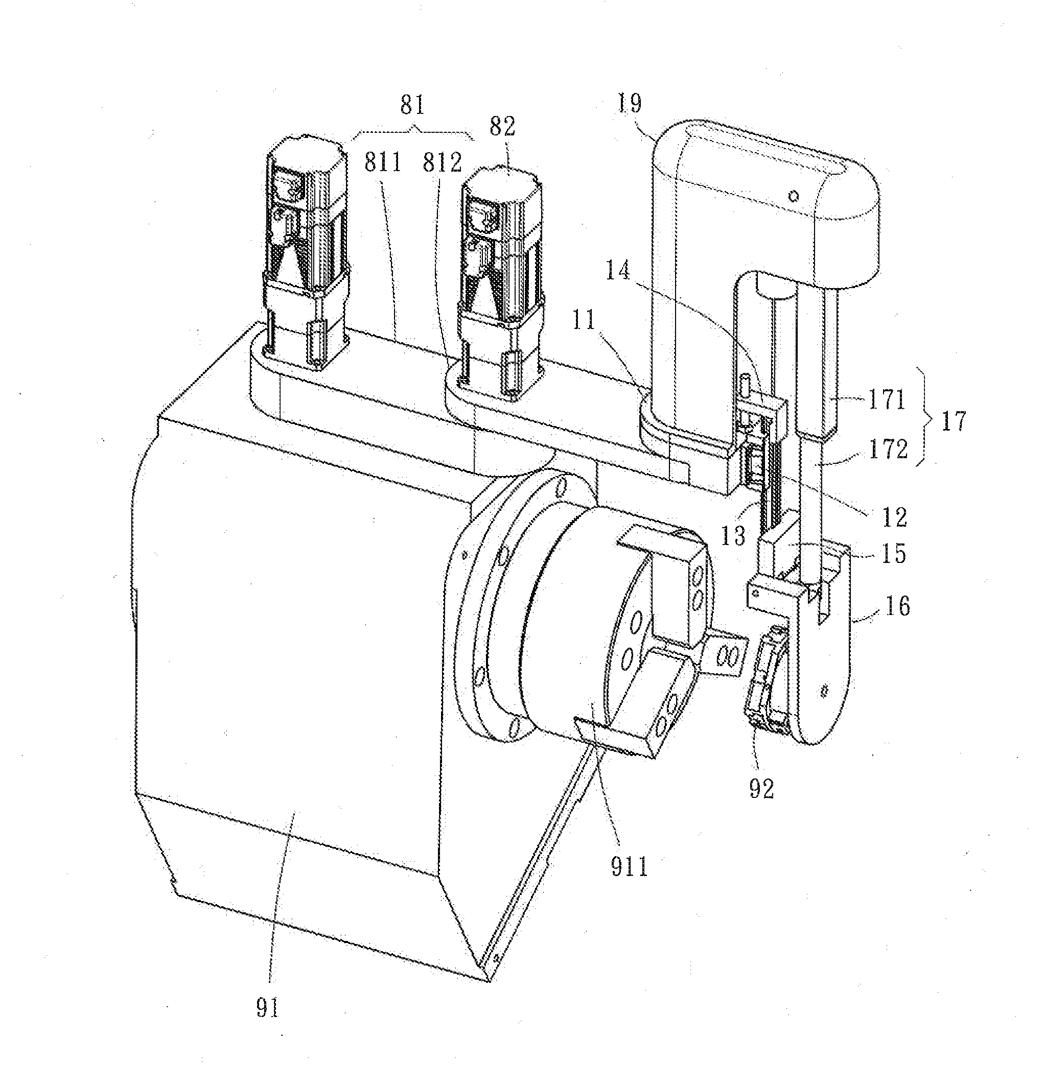
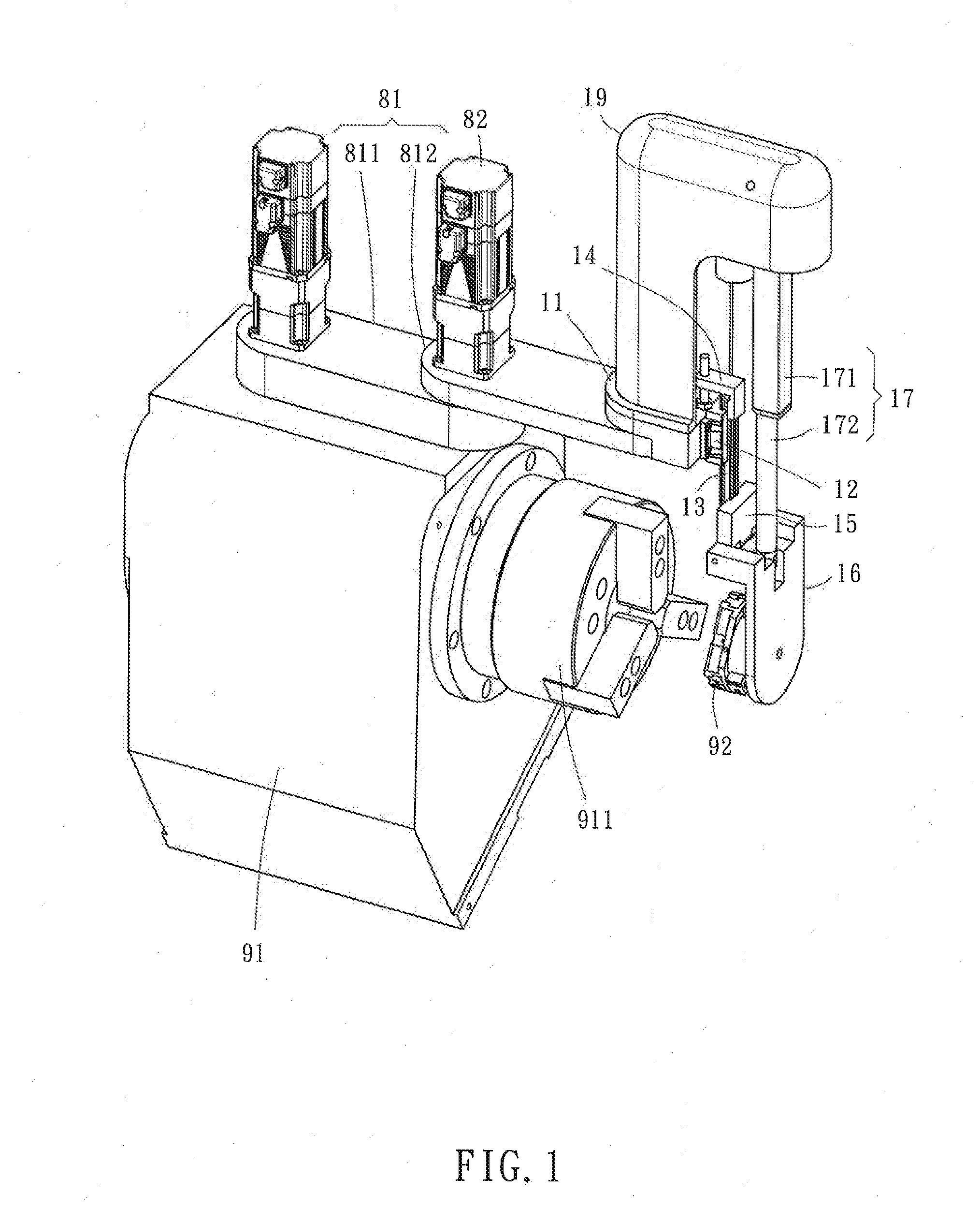
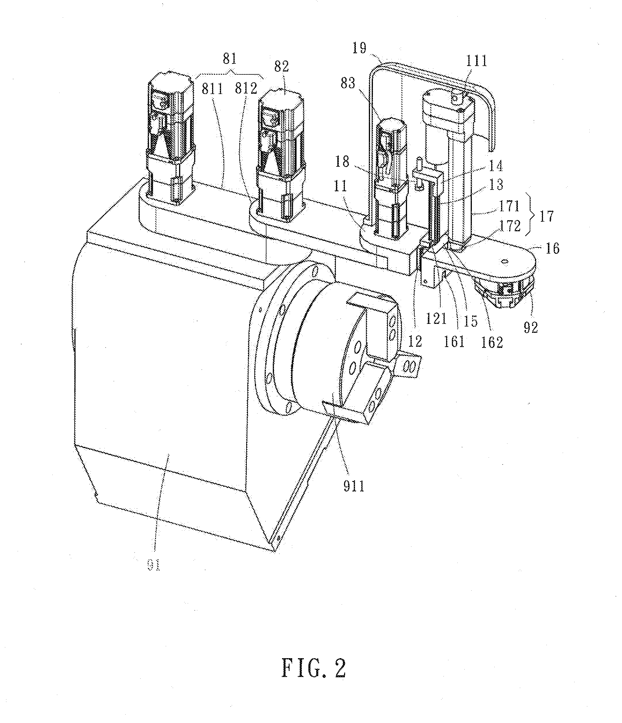
[0017]Referring to FIGS. 1-3, a robotic arm in accordance with the present invention is shown. The robotic arm comprises an arm member 11, a locating member 12, a sliding member 13, a stop member 14, a connector15, a wrist member 16, and a driving device 17.

[0018]It is to be understood that, for easy understanding of the operation of the present invention, the invention is shown installed in a movable arm 81 is formed of pivotally connected first arm segment 811 and second arm segment 812, wherein the first arm segment 811 is pivotally connected to a processing machine 91 and swingable relative to the processing machine 91. It also should be noted that the application of the present invention is not limited to installation in the movable arm 81; the invention can also be directly mounted in a machine tool or object.

[0019]The arm member 11 is pivotally connected to the second arm segment 812 of the movable arm 81, comprising a first pivot connection portion 111 for the connection of ...


PUM


Abstract

In order to reduce the cost of robotic arm, the invention provides a robotic arm, which includes an arm member having a first pivot connection portion, a locating member affixed to the arm member, a sliding member movably mounted at the locating member, a stop member affixed to the sliding member, a wrist member having a second pivot connection portion pivoted to the sliding member and a third pivot connection portion movable relative to the second pivot connection portion, and a driving device including a body member pivoted to the first pivot connection portion and an extension member pivoted to the third pivot connection portion of the wrist member and movable relative to the body member. Using the locating member, the sliding member, the stop member and the wrist member to match with the driving device, the robotic arm achieves the effect of moving and swinging and cost reduction.

Description

BACKGROUND OF THE INVENTION[0001]1. Field of the Invention[0002]The present invention relates to robots, and more particularly to a robotic arm.[0003]2. Description of the Related Art[0004]With the advances in robotic technology, unmanned factory is no longer a distant dream. In robotic technology, especially robotic arms have long been used in many automated factories. For example, Japanese Patent 11-77566 discloses a robotic arm for use in a LCD manufacturing factory to deliver glass substrates. The end-piece of the robotic arm is able to make lifting, swinging and turning-around actions to facilitate gripping a glass substrate. However, in order to make complicated actions, the robotic arm needs to use multiple servomotors, resulting in a high robotic arm manufacturing cost and the indisputable fact that it is really not conducive to using a large amount of robotic arms in a factory. Further, due to the problem of high cost, in some situations where only simple moving and swingin...

Claims


Application Information

Patent Timeline
IPC IPC(8): B25J17/02
CPCY10S901/29B25J17/02B23Q1/4833B23Q1/5475B23Q1/5493B23Q7/04B23Q2707/003B25J9/044Y10T74/20335B23Q1/5431B23B31/39Y10T483/171B25J17/025
Inventor HSIEH, WU-TENG
Owner HIWIN TECH
Why Eureka
Try Eureka