
Operating pedal device for vehicle

Active Publication Date: 2015-02-05
TOYODA IRON WORKS CO LTD
View PDF4 Cites 2 Cited by
  • Summary
  • Abstract
  • Description
  • Claims
  • Application Information

AI Technical Summary

Benefits of technology

The present invention relates to a vehicle operation pedal apparatus that improves the appearance and prevents injury. The hollow pedal arm is formed of two half parts that are joined together, making it difficult to see the joining portion from the driver's seat. The connection plate is securely fixed to the hollow pedal arm using welding, and the position of the connection plate can be easily adjusted for different vehicles. The invention also includes a design that allows for flexibility in the front-rear dimension and width dimension without compromising the connection strength. The invention enhances the appearance and prevents injury by improving the design of the hollow pedal arm and the connection plate.

Problems solved by technology

This makes the hollow pedal arm look unattractive, and causes a possibility that, if a foot or a hand touches the joined portion by mistake, the foot or the hand will be injured.
Thus, the connection holes are formed in, for example, side wall portions of the front half 32, but a front-rear dimension L becomes large, which may increase weight and increase manufacturing cost.
However, it is necessary to dispose a pair of dies 106a, 106b and a discharge passage 110, through which a scrap 108 drops, inside a pair of side walls of the front half 32, and hence a width dimension D becomes large, which also increases the weight and increase the cost.
When the output member is connected with the use of a bifurcated clevis, it is not possible to use a general-purpose clevis due to an increase in the width dimension D, and there is also a possibility that the manufacturing cost will further increase.

Method used


Image

  • Operating pedal device for vehicle
  • Operating pedal device for vehicle
  • Operating pedal device for vehicle

Examples


embodiment

[0036]Hereinafter, an embodiment of the invention will be described in detail with reference to the drawings.

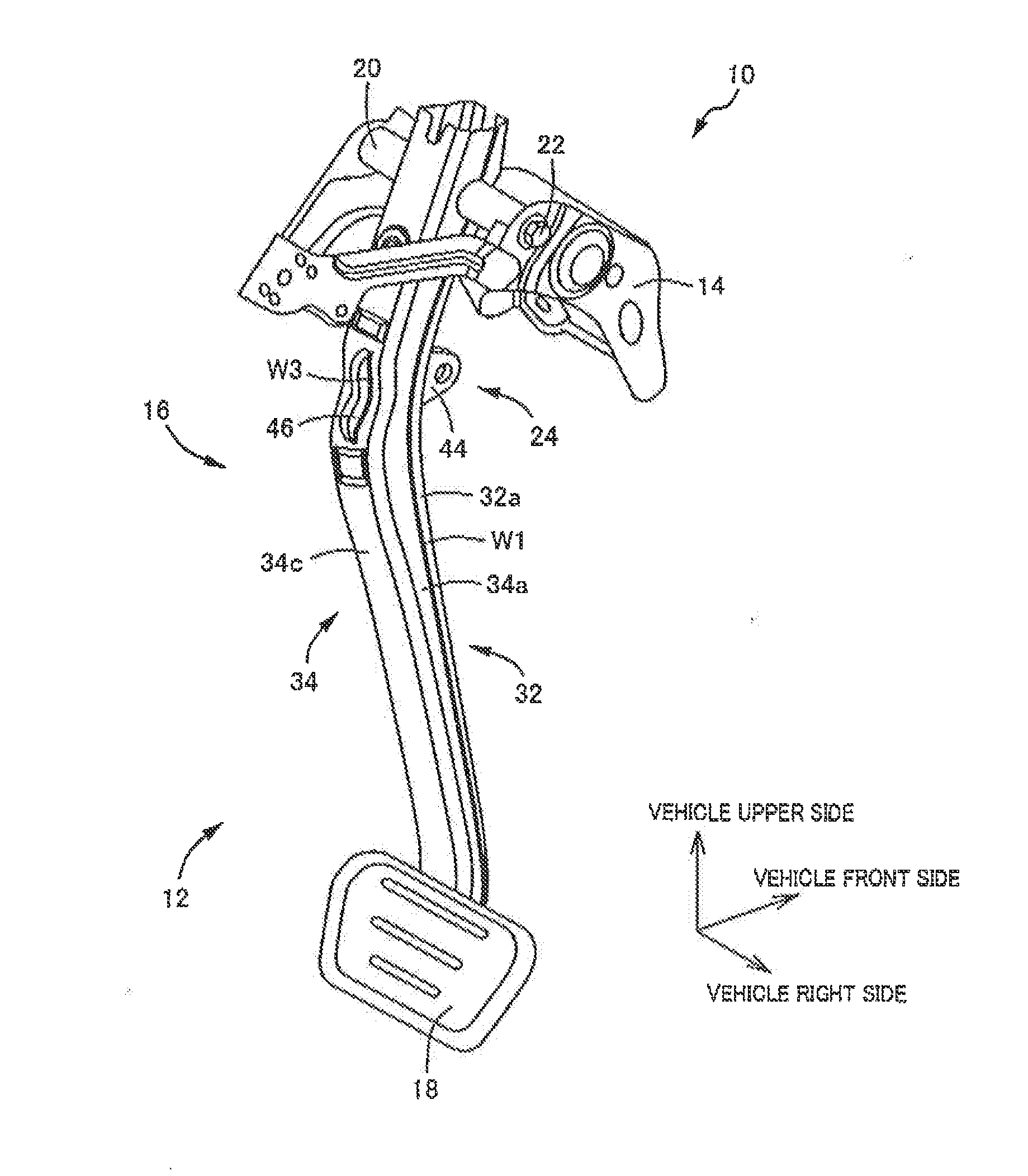
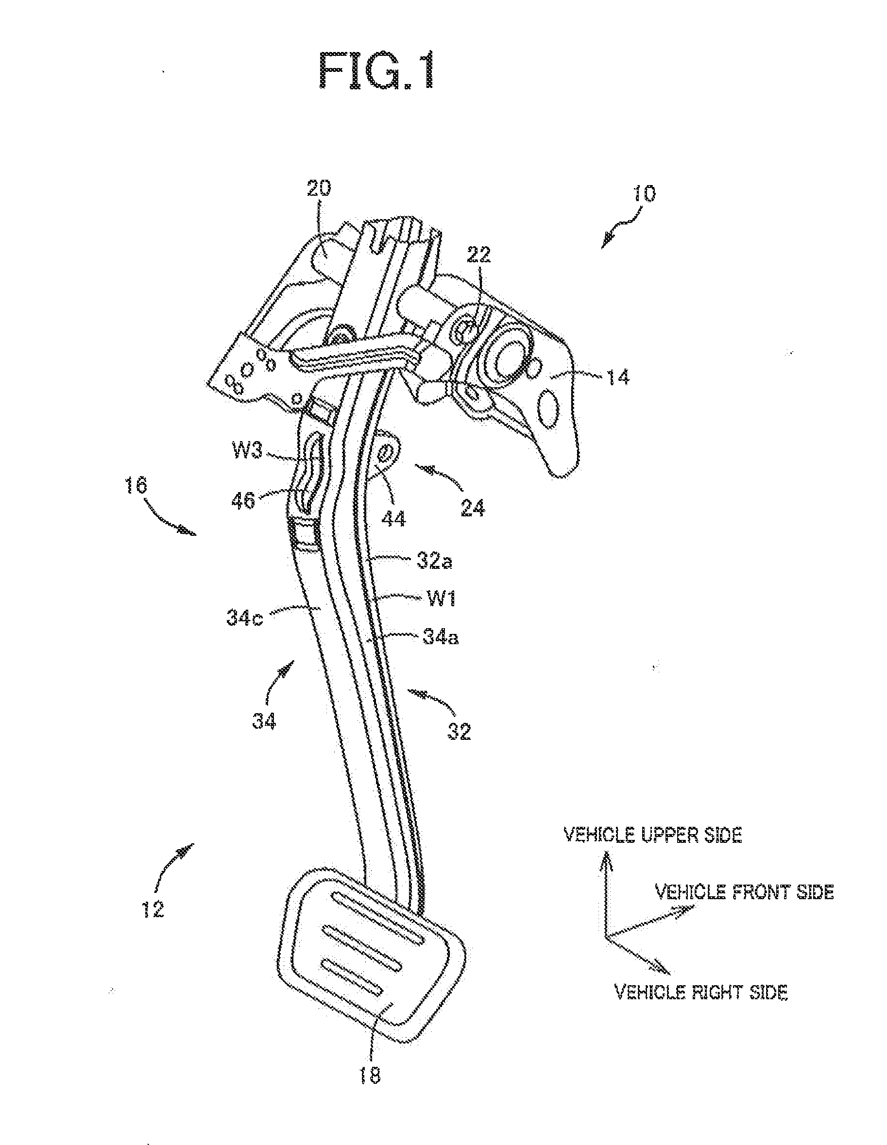
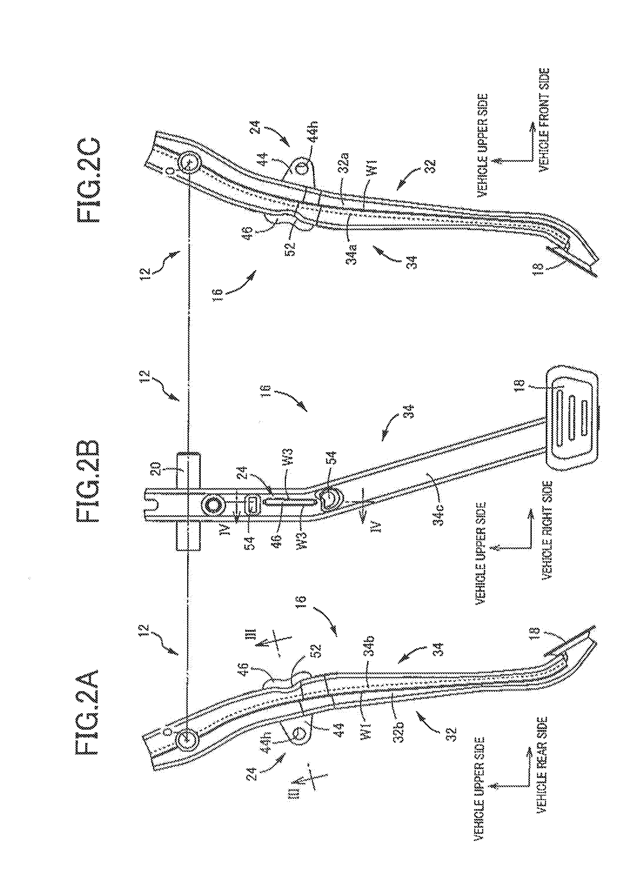
[0037]FIG. 1 is a perspective view illustrating a vehicle operation pedal apparatus 10 to which the invention is applied. The vehicle operation pedal apparatus is a brake pedal apparatus for a service brake, and an operation pedal 12 is movably disposed on a bracket 14 fixedly fitted to a vehicle body. FIG. 2 is an explanatory view of the operation pedal 12, in which FIG. 2(a) is a left side view, FIG. 2(b) is a front view as seen from a driver's seat side, and FIG. 2(c) is a right side view. Further, FIG. 3 is an enlarged sectional view taken along the line III-III in FIG. 2(a), and FIG. 4 is an enlarged sectional view taken along the line IV-IV in FIG. 2(b).

[0038]The operation pedal 12 includes an elongate hollow pedal arm 16 disposed in the up-down direction of a vehicle, and a pedal sheet 18 fixed to a lower end portion of the hollow pedal arm 16 and depressed by a driver...


PUM


Abstract

A vehicle operation pedal apparatus includes an elongate hollow pedal arm provided with a pedal sheet, the vehicle operation pedal apparatus transmits a pedal operating force applied to the hollow pedal arm to an output member connected to the hollow pedal arm. The hollow pedal arm is formed of a pair of a front half and a rear half each having a U-shaped section and combined with each other; the vehicle operation pedal apparatus comprises a plate-shaped connection plate having a connecting portion connected to the output member so as to be pivotable relative to the output member and fixed integrally with the hollow pedal arm; in the front half and the rear half, slit-shaped through-holes are formed, respectively; and the connection plate is passed through the hollow pedal arm in a vehicle front-rear direction through the through-holes.

Description

TECHNICAL FIELD[0001]The invention relates generally to a vehicle operation pedal apparatus, and more specifically to an improvement of a vehicle operation pedal apparatus in which a pair of halves each having a U-shape section are joined together to form a hollow pedal arm.BACKGROUND ART[0002]There has been known a vehicle operation pedal apparatus that includes an elongate hollow pedal arm disposed in an up-down direction of a vehicle and provided with a pedal sheet that is disposed at a lower end portion of the pedal arm and that is depressed toward a vehicle front side, the vehicle operation pedal apparatus transmitting a pedal operating force applied to the hollow pedal arm to an output member that is connected to the hollow pedal arm so as to be pivotable relative to the hollow pedal arm. An example of such an apparatus is described in Patent Document 1. A hollow pedal arm is formed of a pair of halves each having a U-shape (a shallow U-shape with angled corners or a dish shap...

Claims


Application Information

Patent Timeline
IPC IPC(8): G05G1/44
CPCG05G1/44G05G1/50Y10T74/20528
Inventor TSUGUMA, TOMOHIRO
Owner TOYODA IRON WORKS CO LTD
Learn More