Display apparatus and control method for same

a control method and display apparatus technology, applied in the field of display apparatus and control method for same, can solve the problems of brightness non-uniformity, brightness non-uniformity, brightness non-uniformity also in display apparatus, etc., and achieve the effect of suppressing the reduction of image contrast and accurately reducing brightness non-uniformities

Inactive Publication Date: 2015-02-05
CANON KK
View PDF4 Cites 13 Cited by
  • Summary
  • Abstract
  • Description
  • Claims
  • Application Information

AI Technical Summary

Benefits of technology

[0028]The present invention provides technology whereby brightness non-uniformities can be reduced accurately, while suppressing reduction of image contrast.

Problems solved by technology

Display apparatuses of this kind have a problem in that a brightness non-uniformity occurs within the screen.
Brightness non-uniformities occur in display apparatuses which have a light-emitting unit and a display unit, and do not only occur in liquid crystal display apparatuses.
For example, brightness non-uniformities also occur in display apparatuses which use elements different to liquid crystal elements to modulate light from a light-emitting section.
For example, if the input signal level is high, then a brightness non-uniformity occurs which is greatly affected by fluctuation in the light transmission properties of the liquid crystal panel.
If the input signal level becomes lower, then other effects become greater compared to the effect of the fluctuation in the light transmission properties of the panel, and the tendency of the brightness non-uniformity changes.
Similarly, it is not possible to reduce the input gradation level to a value lower than 0.
However, in a method of this kind, there may be increase in brightness non-uniformities, depending on the input signal level.
However, in the method described in Japanese Patent Application Publication No. 2009-128733, it is not possible to sufficiently reduce the brightness non-uniformity if the tendency of the first brightness non-uniformity differs greatly from the tendency of the second brightness non-uniformity.
Therefore, in the method described in Japanese Patent Application Publication No. 2009-128733, although the problem of increase in the second brightness non-uniformity due to reduction in the first brightness non-uniformity can be resolved, it is not possible to reduce both the first brightness non-uniformity and the second brightness non-uniformity sufficiently.

Method used


Image

  • Display apparatus and control method for same
  • Display apparatus and control method for same
  • Display apparatus and control method for same

Examples


first embodiment

General Composition

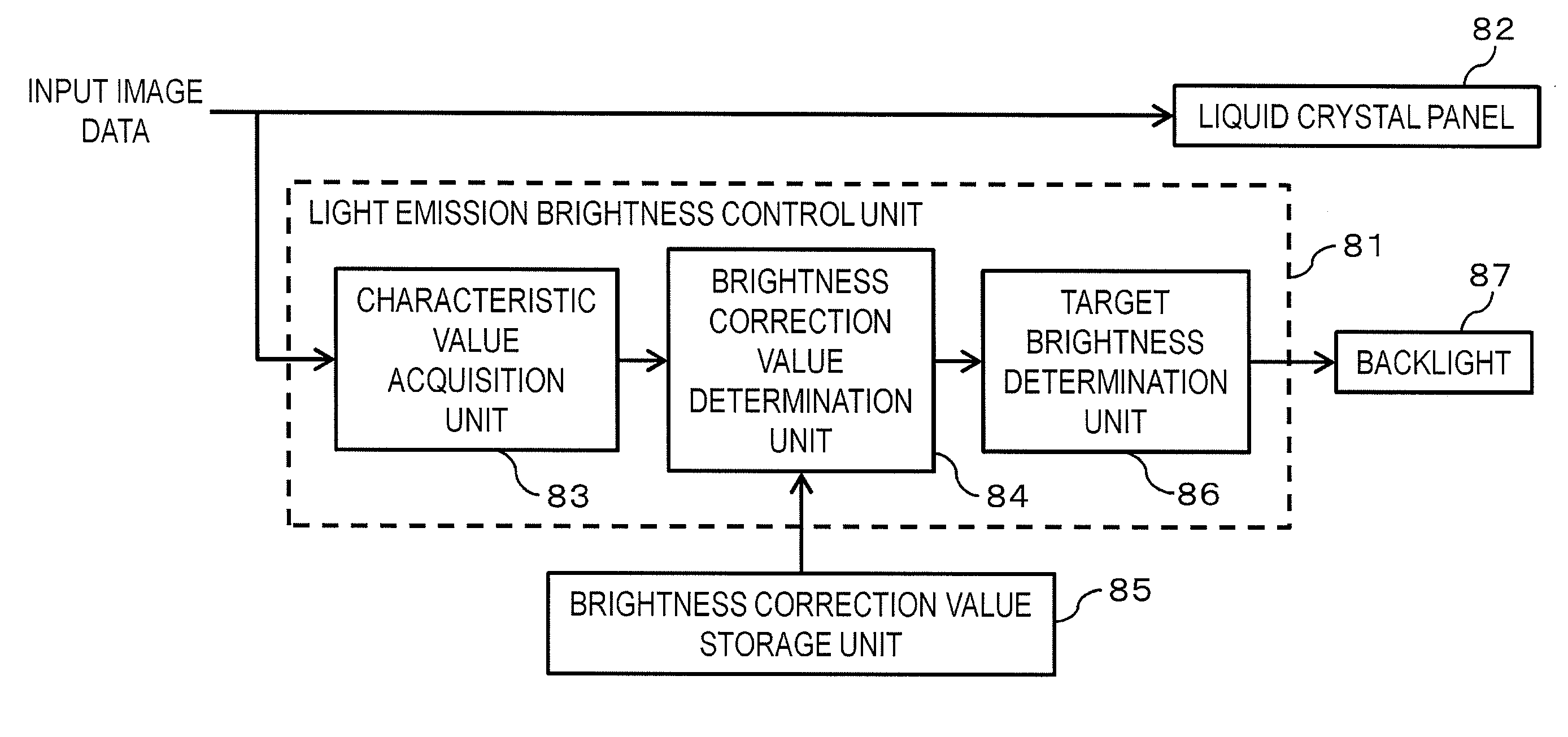
[0061]FIG. 6 is a block diagram showing one example of the functional composition of a liquid crystal display apparatus relating to a first embodiment of the present invention.

[0062]The backlight 87 is a light-emitting unit having a plurality of light sources of which the light emission brightness can be controlled independently. The plurality of light sources are provided on the rear surface side of a liquid crystal panel 82, and the light emitted from the backlight 87 (plurality of light sources) is radiated onto the rear surface of the liquid crystal panel 82. The light source has one or more light-emitting members. For the light-emitting member, it is possible to use an LED, an organic EL element, a cold cathode tube, or the like.

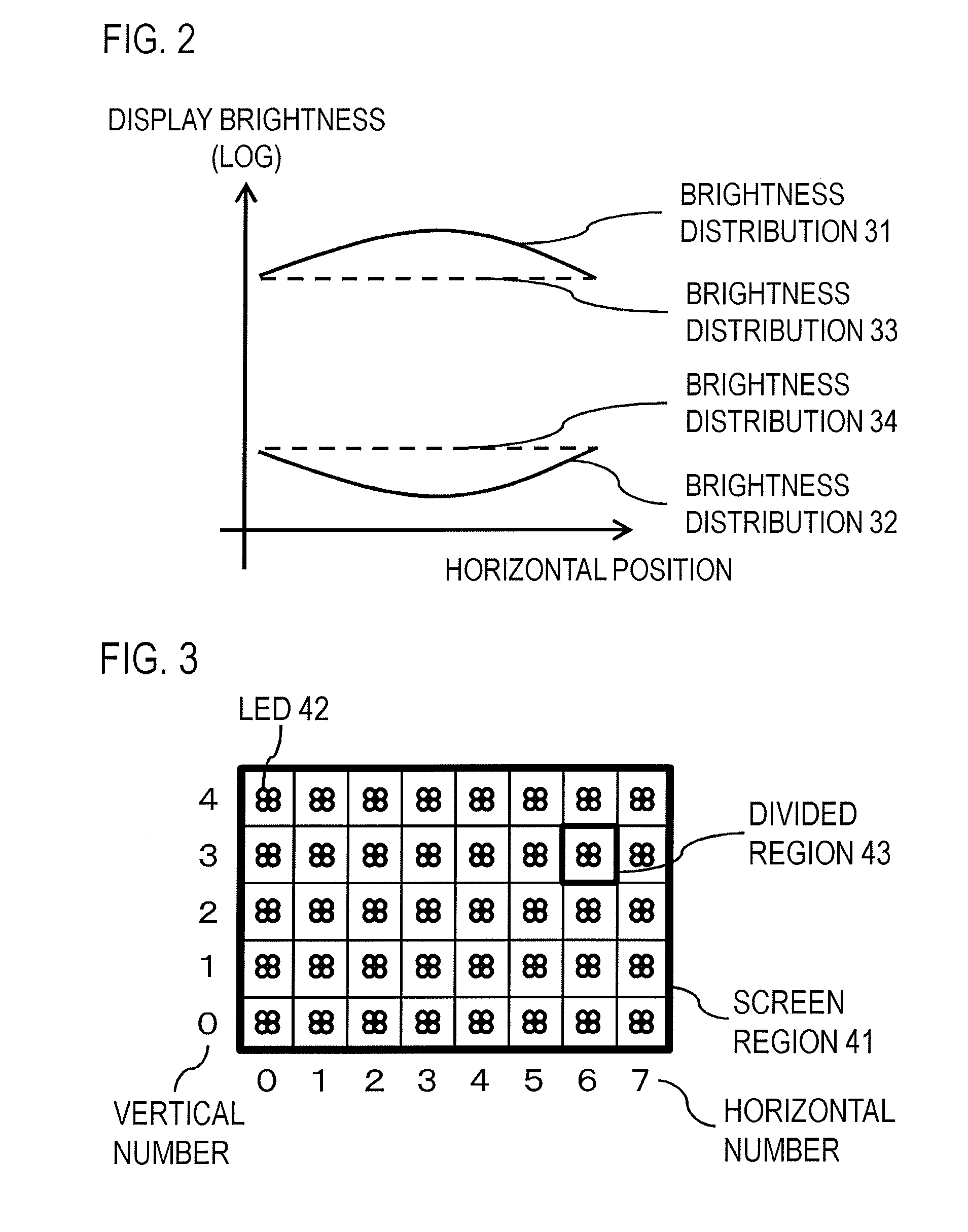
[0063]In the present embodiment, as shown in FIG. 3, light sources are provided respectively in each of the plurality of divided regions which constitute the screen region. In FIG. 3, region 41 denotes the region of the screen, and re...

second embodiment

[0127]The second embodiment is described with respect to a case where the display unit (liquid crystal panel) also has the following characteristics.[0128]Characteristics whereby a third brightness non-uniformity, which has a different tendency to the first brightness non-uniformity and the second brightness non-uniformity, occurs when a uniform image of a gradation level between the first gradation level and the second gradation level, is displayed in a state where the plurality of light sources are emitting light at the same light emission brightness.

[0129]If the gradation level is a gradation level between the first gradation level and the second gradation level, then contrast is not reduced, even if the gradation level is corrected in order to reduce the brightness non-uniformity. Consequently, the third brightness non-uniformity described above is effectively reduced by image processing (correction of the gradation level).

[0130]Therefore, in the present embodiment, an example i...


PUM

PropertyMeasurementUnit
light emission brightnessaaaaaaaaaa
brightnessaaaaaaaaaa
light emission brightnessesaaaaaaaaaa

Abstract

The display apparatus comprises: a light-emitting unit having a plurality of light sources; a display unit configured to display an image on a screen by modulating light from the light-emitting unit; a first storage unit configured to store a first brightness correction value corresponding to a first gradation level, and a second brightness correction value corresponding to a second gradation level; and a control unit configured to determine, by using the first brightness correction value and the second brightness correction value, a brightness correction value corresponding to a gradation level of a display object image data, and control, on the basis of the determined brightness correction value, the light emission brightnesses of respective light sources.

Description

BACKGROUND OF THE INVENTION[0001]1. Field of the Invention[0002]The present invention relates to a display apparatus and a control method for same.[0003]2. Description of the Related Art[0004]There are display apparatuses which have a light-emitting unit and a display unit (display panel) that displays an image on a screen by modulating the light from the light-emitting unit. Display apparatuses of this kind have a problem in that a brightness non-uniformity occurs within the screen.[0005]There follows a description of a transmissive type liquid crystal display apparatus having a backlight and a liquid crystal panel which displays an image on a screen by transmitting light from the backlight.[0006]Brightness non-uniformities occur in display apparatuses which have a light-emitting unit and a display unit, and do not only occur in liquid crystal display apparatuses. For example, brightness non-uniformities also occur in display apparatuses which use elements different to liquid cryst...

Claims


Application Information

Patent Timeline
Patent Type & Authority Applications(United States)
IPC IPC(8): G09G3/34G09G3/36G02F1/1335
CPCG09G3/342G02F1/1336G09G2320/0646G09G2320/0233G09G2320/062G09G3/36G02F1/133611
Inventor OOYA, TSUYOSHI
Owner CANON KK
Why Eureka
Try Eureka