Image forming apparatus and manufacturing method for the same

a technology of image forming apparatus and manufacturing method, which is applied in the direction of electrographic process apparatus, line/current collector details, instruments, etc., can solve the problems of electric connection failure between, work will become inability to visually observe the coil spring, etc., and achieve the effect of preventing the occurrence of electric connection failur

Active Publication Date: 2015-02-05
BROTHER KOGYO KK
View PDF2 Cites 16 Cited by
  • Summary
  • Abstract
  • Description
  • Claims
  • Application Information

AI Technical Summary

Benefits of technology

[0007]Aspects of the present invention are advantageous in that they provide an image forming apparatus and a manufacturing method thereof capable of preventing occurrence of electric connection failure between a connection electrode and a power source substrate.

Problems solved by technology

However, when a worker moves the power source substrate to approach the coil spring, the work will become unable to visually observe the coil spring.
In this case, there is a possibility that the power source substrate is attached to the frame body in a state where a connection electrode contacting the power source substrate is buckled, and thereby electric connection failure occurs between an electrode of the coil spring and the power source substrate.

Method used


Image

  • Image forming apparatus and manufacturing method for the same
  • Image forming apparatus and manufacturing method for the same
  • Image forming apparatus and manufacturing method for the same

Examples


first embodiment

[0027]Hereafter, a first embodiment is explained with reference to FIGS. 1 to 10.

[0028]1. Overall Configuration of Printer

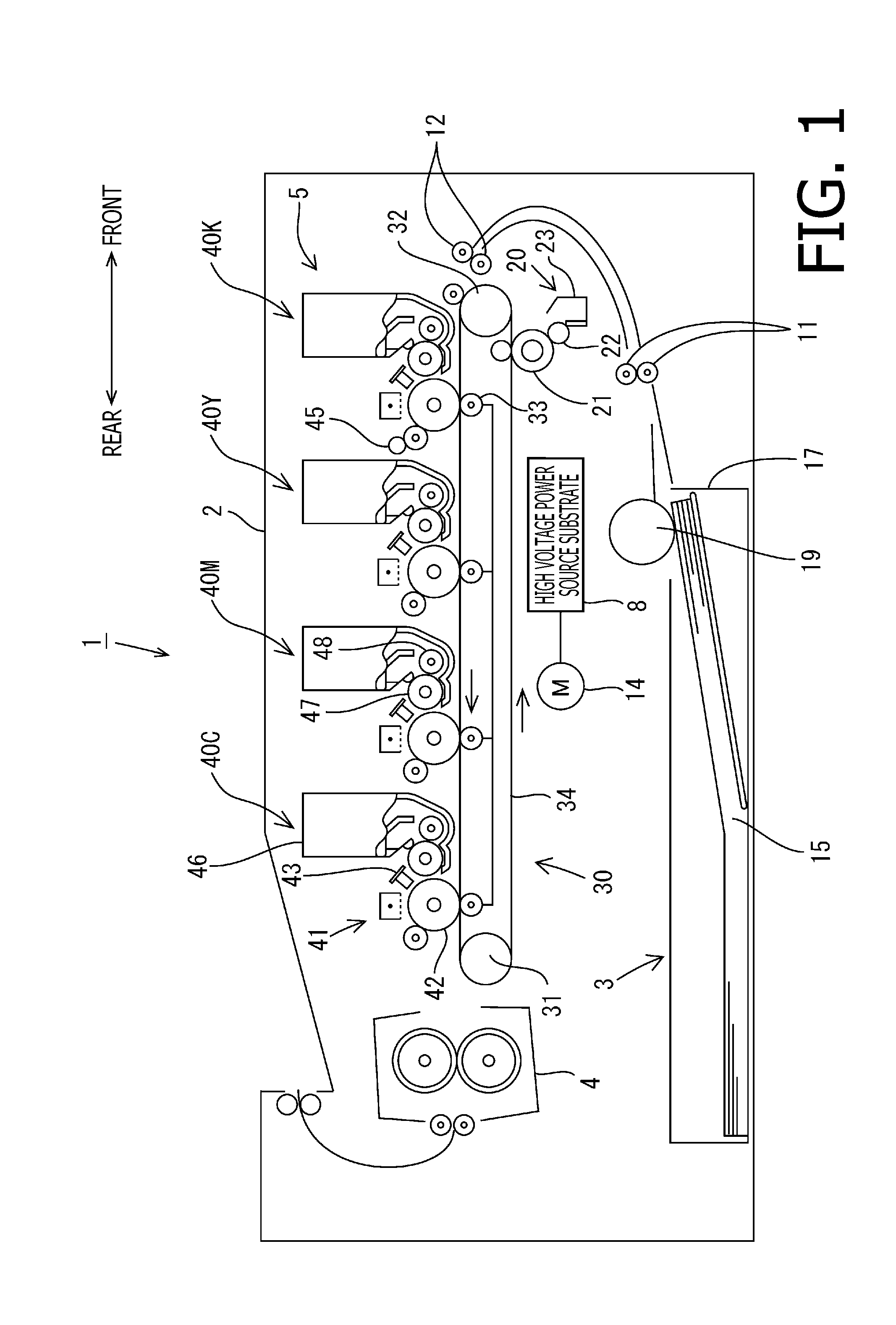
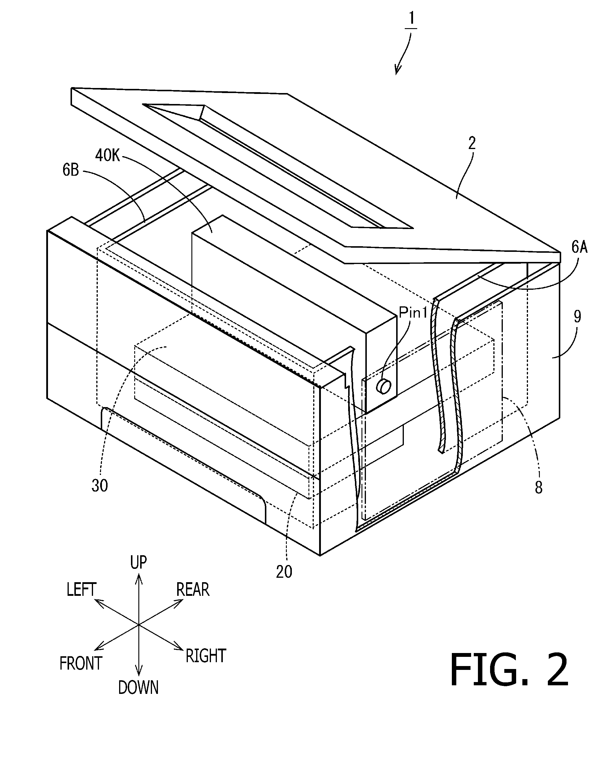
[0029]A color printer 1 shown in FIG. 1 is an example of an image forming apparatus. In the following explanation, when components are explained separately in regard to colors, suffixes of Y (yellow), M (magenta), C (cyan) and K (black) are added to such components, respectively. On the other hand, when such components are explained without differentiating in regard to colors, such suffixes are omitted. It is understood that the image forming apparatus is not limited to a color printer, but may be a multifunction peripheral having the facsimile function and the copying function, or a monochrome printer.

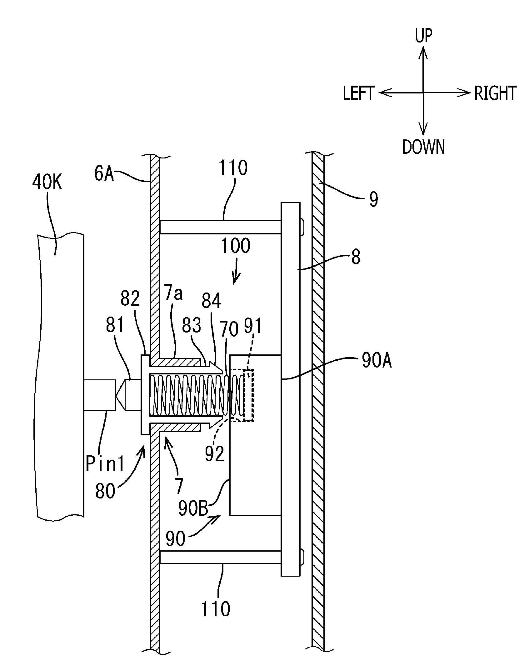
[0030]The color printer (hereafter, simply referred to as a “printer”) 1 includes, in a body casing, a paper supply unit 3, a fixing unit 4, an image formation unit 5, a belt cleaning head 20, a belt unit 30, a high voltage power unit 50 and a frame (6A and 6B). Th...

second embodiment

[0078]Hereafter, a second embodiment is described with reference to FIGS. 11 to 13. Since the second embodiment is different from the first embodiment in regard to only the configuration of the insertion part of the second conductive member, the following explanation focuses on the difference with respect to the first embodiment.

[0079]As shown in FIG. 11, a second conductive member 80A according to the second embodiment includes a contacting part 81, a flange part 82 and a fixing part 85 formed in a cylindrical shape. On an outer circumferential surface of the fixing part 85, a male thread part 85a is formed. The flange part 82 and the male thread part 85a are formed integrally. The contacting part 81 has a wide diameter part 81a, and is formed separately from the flange part 82 and the male thread part 85a.

[0080]The flange part 82 has a through hole 82a into which the contacting part 81 is inserted. As shown in FIG. 11, the contacting part 81 is used in a state where the contactin...


PUM

PropertyMeasurementUnit
charge voltageaaaaaaaaaa
voltageaaaaaaaaaa

Abstract

An image forming apparatus, comprising: a frame body to which an attachment unit is detachably attachable, the attachment unit being configured to have an input electrode and to be used for image formation on a recording medium; a power source substrate configured to have an output electrode for outputting a voltage and to be attached to the frame body from an opposite side with respect to a side on which the attachment unit is attached; and a connection electrode configured to electrically connect the output electrode to the input electrode of the attachment unit, wherein the frame body comprises an insertion part into which the connection electrode is inserted from an opposite side with respect to a side on which the power source substrate is attached.

Description

CROSS-REFERENCE TO RELATED APPLICATION[0001]This application claims priority under 35 U.S.C. §119 from Japanese Patent Application No. 2013-159369, filed on Jul. 31, 2013. The entire subject matter of the application is incorporated herein by reference.BACKGROUND[0002]1. Technical Field[0003]Aspects of the present invention relate to an image forming apparatus and a manufacturing method for the image forming apparatus, and particularly to a technology for attaching a power source substrate to the image forming apparatus.[0004]2. Related Art[0005]In general, in an image forming apparatus, a power source substrate is provided. For example, a power source substrate is attached to a frame body of an image forming apparatus such that a coil spring attached to the frame body is covered by the power source substrate.SUMMARY[0006]However, when a worker moves the power source substrate to approach the coil spring, the work will become unable to visually observe the coil spring. In this case,...

Claims


Application Information

Patent Timeline
Patent Type & Authority Applications(United States)
IPC IPC(8): G03G15/00H01R43/00
CPCG03G21/1652G03G15/80G03G21/1867Y10T29/49174
Inventor HAMAYA, MASAHITOUENO, SHIRO
Owner BROTHER KOGYO KK
Why Eureka
Try Eureka