
Circuit module

A technology for circuit modules and module substrates, which can be applied to circuits, electrical components, electrical solid devices, etc., and can solve the problems of reduced driving capacity, energy consumption, and temperature rise in the active area.

Inactive Publication Date: 2009-04-01
SANYO ELECTRIC CO LTD +1
View PDF0 Cites 11 Cited by
  • Summary
  • Abstract
  • Description
  • Claims
  • Application Information

AI Technical Summary

Problems solved by technology

[0007] The above-mentioned electronic equipment, especially semiconductor devices, will generate heat due to operation, which will increase the temperature of the active area, resulting in a decrease in driving capability
And if you want to improve its driving ability, it will consume more energy

Method used


Image

  • Circuit module
  • Circuit module
  • Circuit module

Examples


Embodiment Construction

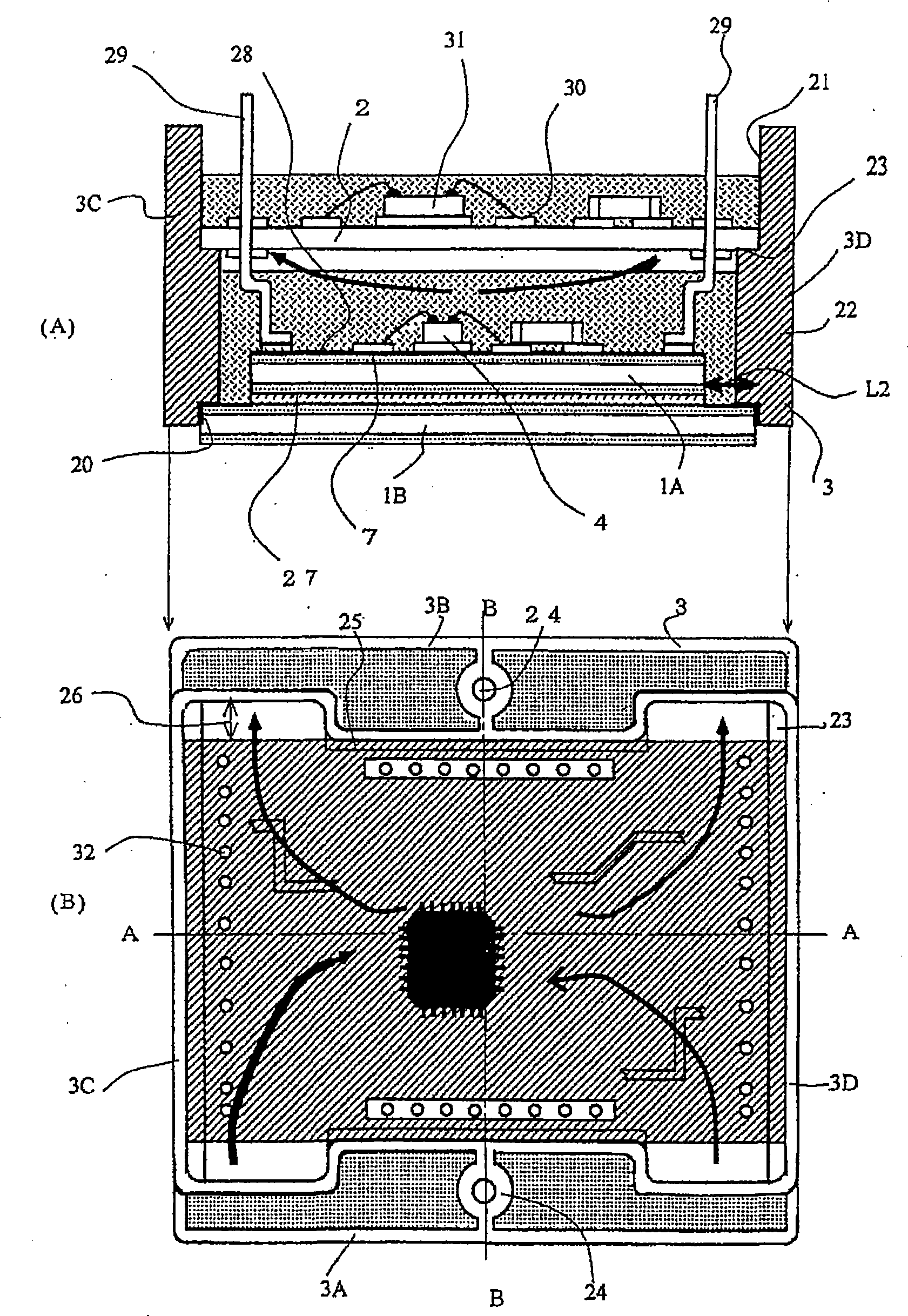
[0062] Below, before describing the embodiments of the present invention, refer to figure 1 , Figure 7 The outline of the present invention will be described.

[0063] figure 1 and Figure 7 The largest difference is: compared to Figure 7 Realized by metal substrate 1 and resin substrate 2, figure 1 Two metal substrates are used. The lower metal substrate 1B is a base substrate and is formed larger than the entire circumference of the upper first substrate 1A by L2. This distance L2 is called a surface extension distance, and can improve the withstand voltage characteristics of the first substrate 1A and the rear surface of the base substrate 1B when an actual circuit module is formed.

[0064] then enter figure 1 description, where only the first substrate 1A is Figure 7 The difference is the metal substrate 1, and the rest of the composition is the same (please refer to the description of the paragraph of the prior art).

[0065] First, the case material 3 will b...


PUM


Abstract

To improve reliability of a circuit module by improving heat release performance and minimizing thermal influence on a device to be mounted, a base substrate having a first substrate mounted thereon is fitted into a lower portion of casing member, and a second substrate is installed in the upper portion of the casing member so that a spaced area can be provided. In addition, a drive device to be installed on the second substrate is positioned off the center of the second substrate.

Description

technical field [0001] The present invention relates to circuit modules for handling large electric power. Background technique [0002] In recent years, newspapers and magazines have reported environmental damage, signs of global warming, and the causes of this warming. Although there are various reasons for this, the increase in power consumption is one of them. Since most of the aforementioned electricity is dependent on depleting oil, the release of carbon dioxide gas into the atmosphere from the burning of this oil is a problem. In addition, almost all cars are gasoline engine cars is also one of the reasons. [0003] Of course, the aforementioned electric power is required to drive electronic machines all over the world. It becomes a power source for washing machines, air conditioners, mobile devices, etc., and is necessary for human beings on the earth to maintain a civilized life, so it is a very difficult problem to solve. [0004] On the other hand, the car bec...

Claims


Application Information

Patent Timeline
Patent Type & Authority Applications(China)
IPC IPC(8): H01L25/00H01L25/16H01L23/367
CPCH01L2224/48091H01L25/162H01L2224/48465H01L2224/48227H01L2924/19105H01L2924/3025H01L2924/13055H01L2924/00014H01L2924/00
Inventor 坂本英行西塔秀史小池保広月泽正雄
Owner SANYO ELECTRIC CO LTD
Learn More