Cleaning device for on-vehicle optical sensor

a cleaning device and optical sensor technology, applied in the direction of vehicle cleaning, cleaning process and apparatus, cleaning using liquids, etc., can solve the problems of obstructing image capture and substantially reducing the image capture range of the on-board optical sensor

Active Publication Date: 2015-02-12
DENSO CORP
View PDF8 Cites 70 Cited by
  • Summary
  • Abstract
  • Description
  • Claims
  • Application Information

AI Technical Summary

Problems solved by technology

In this case, the discharge port (distal portion of nozzle) may obstruct image capturing.
This may subst...

Method used


Image

  • Cleaning device for on-vehicle optical sensor
  • Cleaning device for on-vehicle optical sensor
  • Cleaning device for on-vehicle optical sensor

Examples


first embodiment

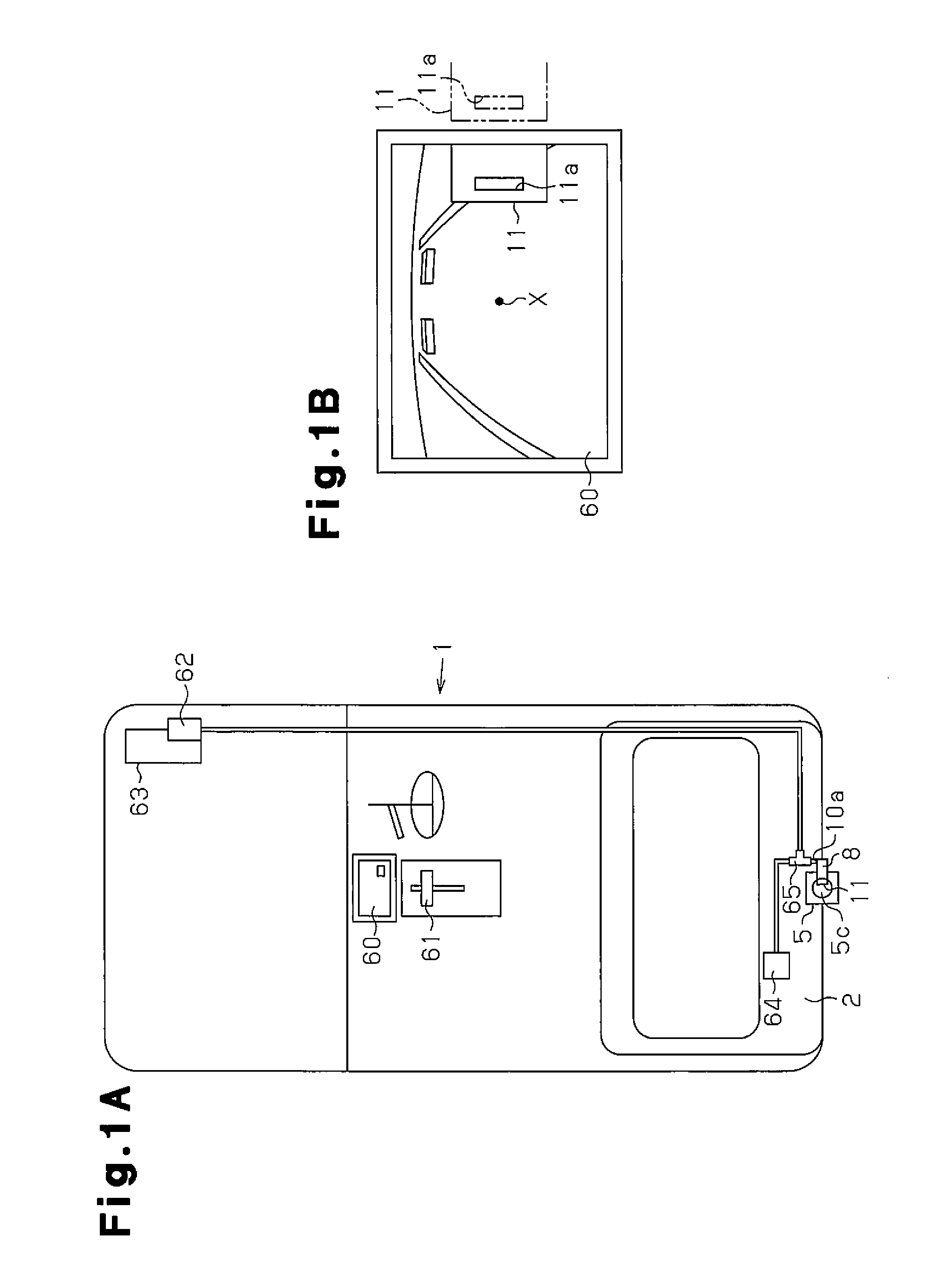
[0030]A first embodiment of an on-board optical sensor cleaning device mounted on a vehicle will now be described with reference to FIGS. 1 to 5.

[0031]As shown in FIG. 1A, the rear of a vehicle 1 includes a back door 2.

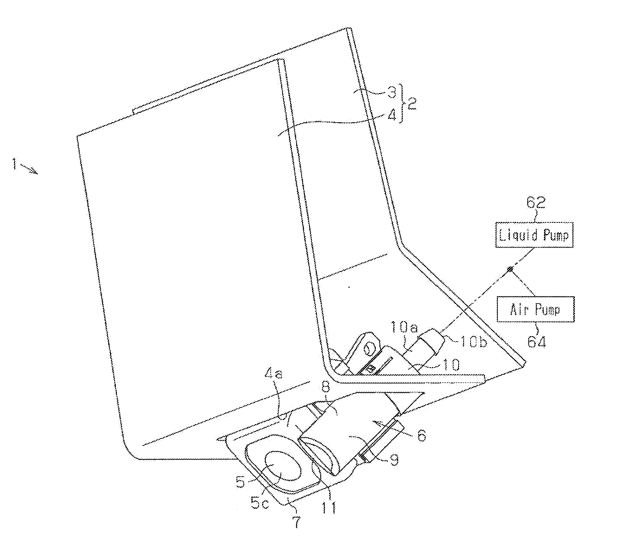
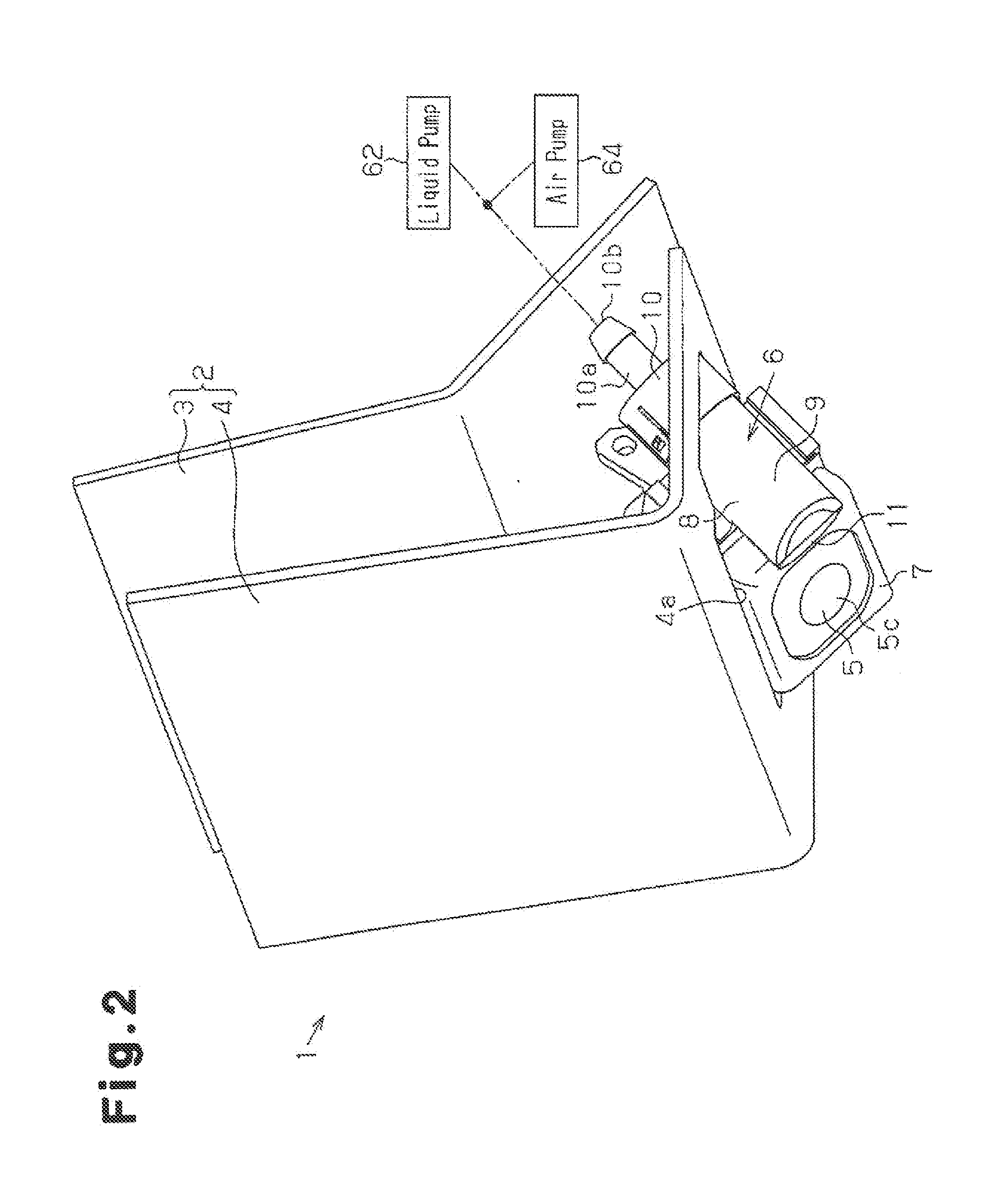
[0032]As shown in FIG. 2, the back door 2 includes a metal vehicle panel 3 and a plastic garnish 4 partially covering the vehicle panel 3. The garnish 4 includes an opening 4a that opens toward the lower side. The back door 2 includes an on-board camera 5, which serves as an on-board optical sensor, and a cleaning unit 6. A portion of the on-board camera 5 and a portion of the cleaning unit 6 are exposed from the opening 4a. The on-board camera 5 is fixed to the vehicle panel 3.

[0033]As shown in FIGS. 3 to 5, the on-board camera 5 includes a generally box-shaped main body 5a, which accommodates an image capturing element (not shown), and a lens 5c, which is arranged in one surface of the main body 5a and serves as an external image capturing surface. The lens 5c is im...

second embodiment

[0062]A second embodiment of an on-board optical sensor cleaning device mounted on a vehicle will now be discussed with reference to FIGS. 6 to 8. In this example, the entire structure of the vehicle 1 is the same as the first embodiment. Thus, same reference numerals are given to those components that are the same as the corresponding components of the first embodiment. Such components will not be described in detail. The on-board camera 5 of this example includes a generally box-shaped main body 5a, which accommodates an image capturing element (not shown), a tube 5b, which extends from one surface of the main body 5a, and a lens 5c, which covers the distal end of the tube 5b and serves as an external image capturing surface.

[0063]Referring to FIGS. 6 and 7, in the present embodiment, a camera-incorporated cleaning unit 21, which includes the on-board camera 5, is fixed to the back door 2.

[0064]The camera-incorporated cleaning unit 21 includes a generally box-shaped unit case 22 a...


PUM


Abstract

An on-board optical sensor cleaning device includes an on-board camera and a discharge port. The on-board camera is mounted on a vehicle. The on-board camera includes a lens. The discharge port discharges fluid toward the lens. The discharged fluid removes foreign material collected on the lens. The lens and the discharge port are relatively movable. At least one of the lens and the discharge port is movable between a cleaning position, where the discharge port is located proximal to an image capturing range center of the on-board camera, and a non-cleaning position, where the discharge port is located farther from the image capturing range center than the cleaning position.

Description

BACKGROUND OF THE INVENTION[0001]The present invention relates to an on-vehicle optical sensor cleaning device.[0002]On-board optical sensors are now often arranged on the front or rear of vehicles to use the images captured by the on-board optical sensors. Foreign material such as mud may collect on an external image capturing surface (lens or protective glass) of such an on-board optical sensor. Thus, an on-board optical sensor cleaning device has been proposed to discharge liquid toward an external image capturing surface from a discharge port of a nozzle (refer to, for example, Japanese Laid-Open Patent Publication No. 2007-53448).[0003]However, in an on-board optical sensor cleaning device such as that described above, the discharge port (distal portion of nozzle) may be located near the center of the image capturing range of the on-board optical sensor so that the discharge port faces the central portion of the external image capturing surface. In this case, the discharge port...

Claims


Application Information

Patent Timeline
IPC IPC(8): B60S1/56B60R1/00B60S1/52
CPCB60S1/56B60S1/52B60R2300/10B60R2300/802B60R1/00B60S1/54B60S1/528
Inventor KIKUTA, TOMOYUKIMATSUSHITA, YUKIHIROSAITO, KEITA
Owner DENSO CORP
Why Eureka
Try Eureka