Automobile wheel

a technology for wheels and wheels, applied in the direction of disc wheels, road vehicles, spoke wheels, etc., can solve the problem that the automobile wheel cannot achieve high rigidity, achieve the effect of satisfying rigidity, increasing the rigidity of the distal end side of each spoke portion, and maintaining the cooling performance of the braking devi

Active Publication Date: 2015-02-12
CENTRAL MOTOR WHEEL CO LTD
View PDF2 Cites 11 Cited by
  • Summary
  • Abstract
  • Description
  • Claims
  • Application Information

AI Technical Summary

Benefits of technology

[0030]In each spoke portion, the outer edge of each spoke projecting thread in the spoke widthwise direction is bent outward in the spoke widthwise direction. Thus, the spoke projecting thread and the inter-spoke plate portion are coupled together on the distal end side of the spoke portion, and the reinforcing plate portion is formed in a region from the portion coupled to the inter-spoke plate portion to the proximal end side (proximal end side of the spoke portion) so as to protrude toward the opening from the outer edge of the spoke projecting thread in the spoke widthwise direction. The reinforcing plate portion is formed into a plate surface continuous with the inter-spoke plate portion. Further, the reinforcing plate portion and the inter-spoke plate portion form a continuous plate surface at a position on the wheel axially back side with respect to the top of the spoke projecting thread. With this configuration, the spoke portion and the inter-spoke plate portion are coupled extremely firmly. As a result, the coupling portion (bent portion) between the spoke portion and the inter-

Problems solved by technology

As a result, the automobile whe

Method used


Image

  • Automobile wheel
  • Automobile wheel
  • Automobile wheel

Examples


Embodiment Construction

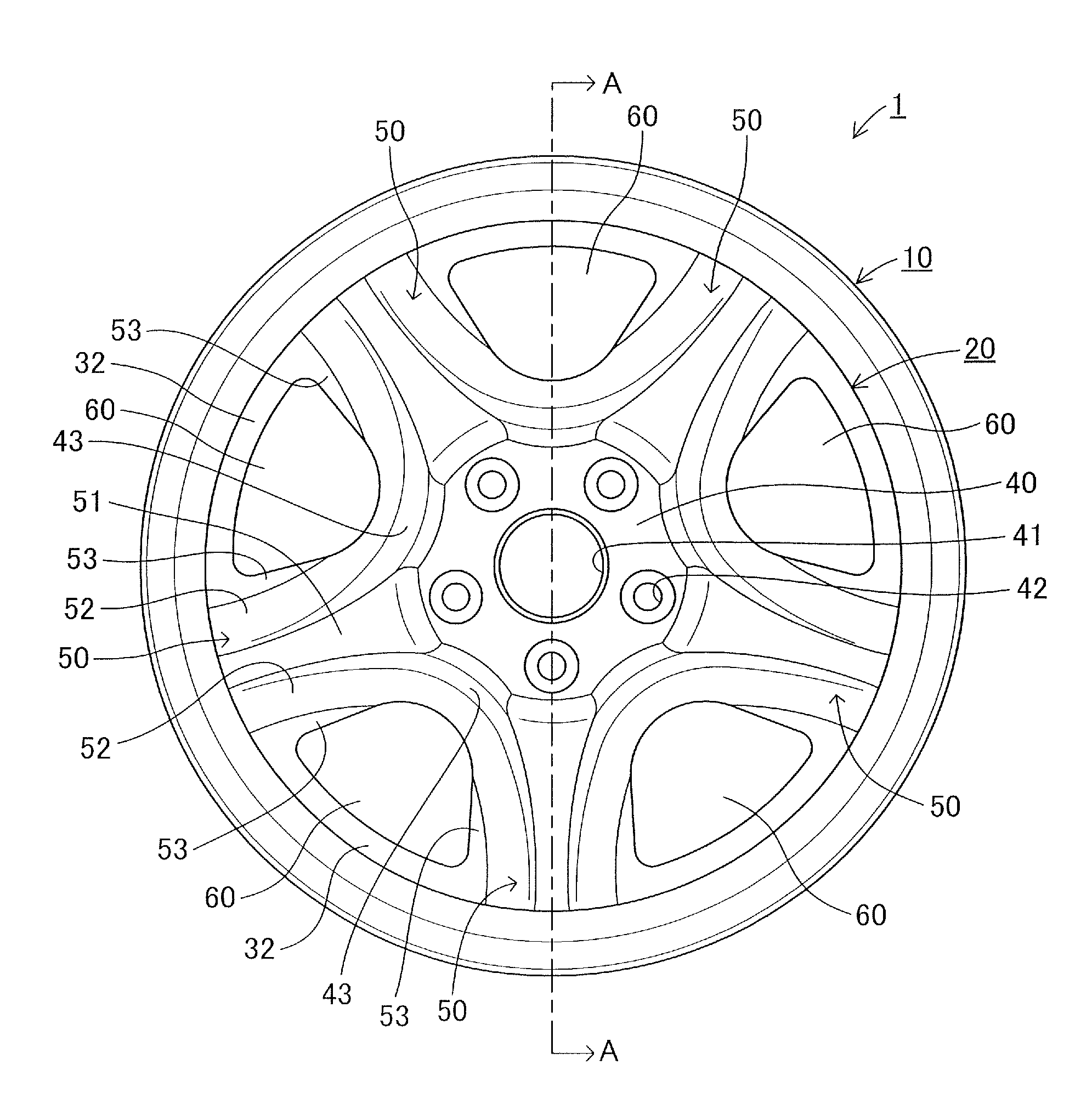
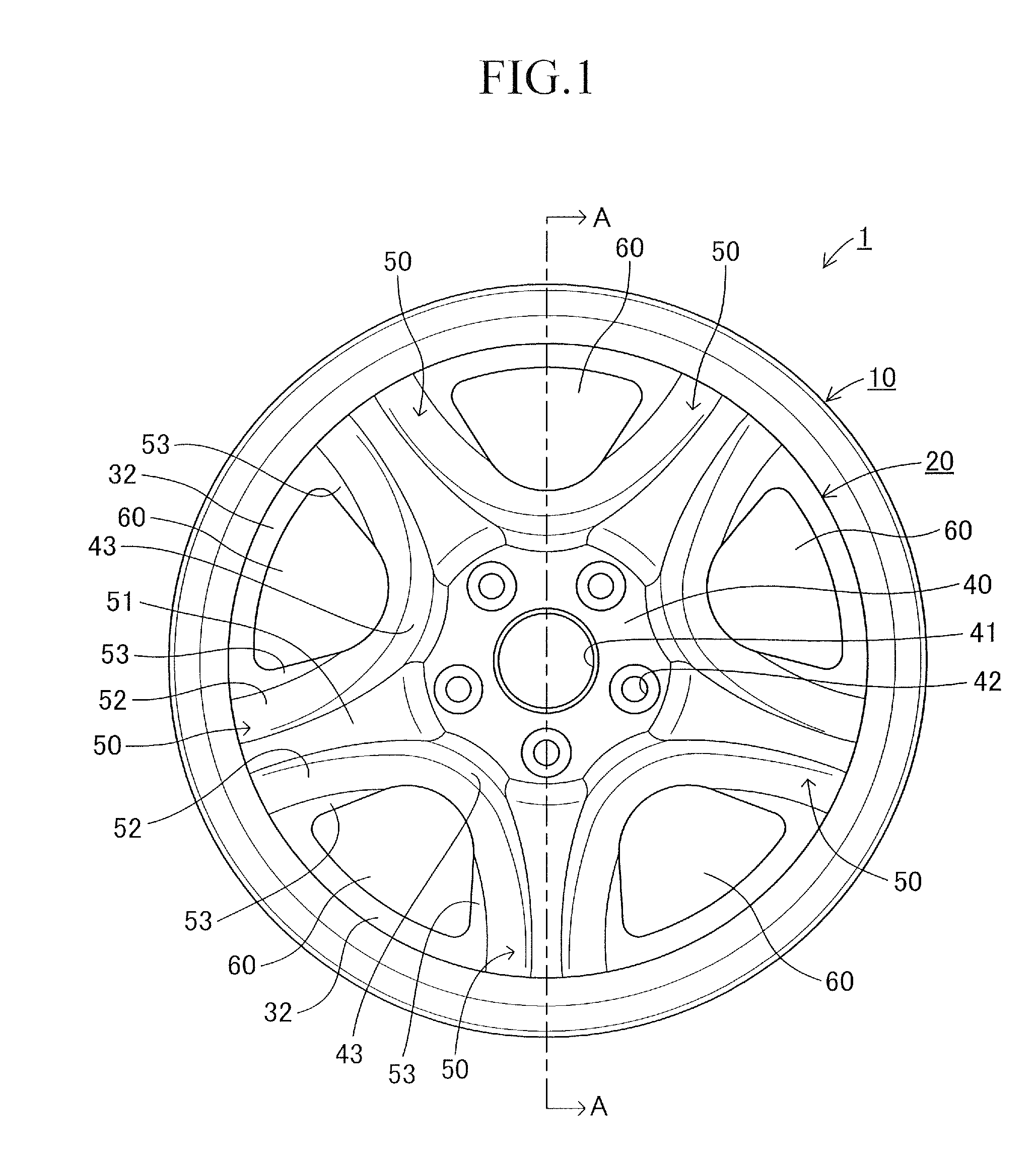
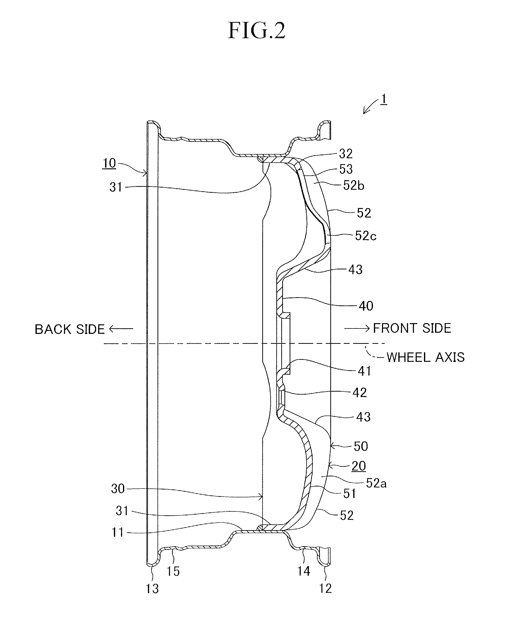
[0052]Now, an embodiment of the present invention is described in detail with reference to the drawings. FIGS. 1 to 3 and FIGS. 9 to 11 illustrate an automobile wheel according to this embodiment. FIGS. 4 and 5 illustrate a wheel disc as a component of the automobile wheel according to this embodiment. Note that, FIGS. 10 and 11 illustrate a curved shape of the automobile wheel of FIGS. 1 and 3 using shading, respectively. An automobile wheel 1 is a steel wheel of a two-piece type including a wheel rim 10 formed by butt welding and shaping a steel flat plate, and a wheel disc 20 similarly formed by shaping a steel flat plate. As illustrated in FIG. 2, the automobile wheel 1 is integrally formed in such a manner that, after a flange portion 30 (hereinafter referred to as “disc flange portion 30”) of the wheel disc 20 is fitted on an inner peripheral surface of a well portion 11 that serves as a cylindrical portion of the wheel rim 10 having a smallest diameter, a distal end region of...


PUM


Abstract

Each spoke portion includes spoke projecting threads on both sides thereof, and a reinforcing plate portion is formed so as to protrude from a side edge of each of the spoke projecting threads outward in a spoke widthwise direction. The reinforcing plate portion is formed continuously with an inter-spoke plate potion extended from a fitting portion of a disc flange portion to a wheel radially inner side, and forms an integral plate surface with the inter-spoke plate portion. With this configuration, it is possible to reduce imbalance of rigidity of the spoke portion in a radial direction, and to increase rigidity of an automobile wheel.

Description

TECHNICAL FIELD[0001]The present invention relates to an automobile wheel formed by joining a wheel disc and a wheel rim together.BACKGROUND ART[0002]Hitherto, a two-piece type automobile wheel including a wheel disc and a wheel rim is integrally formed in such a manner that an outer peripheral surface of a disc flange portion formed on an outer periphery of the wheel disc is fitted and welded on an inner peripheral surface of the wheel rim. As the above-mentioned automobile wheel, as proposed in, for example, Patent Literature 1, there has been known an automobile wheel having a plurality of spokes formed in the wheel disc. In the wheel disc of the automobile wheel, the plurality of spoke portions are extended equiangularly to a wheel radially outer side from an outer peripheral edge of a hub mounting portion to be coupled to a hub of an axle, and the plurality of spoke portions couple the hub mounting portion and the disc flange portion together. With this configuration, in the wh...

Claims


Application Information

Patent Timeline
IPC IPC(8): B60B3/12B60B3/00B60B3/10
CPCB60B3/12B60B2900/311B60B3/007B60B3/10B60B1/10B60B3/004B60B3/005B60B3/02B60B3/041B60Y2200/10
Inventor GOTO, YOSHIFUMI
Owner CENTRAL MOTOR WHEEL CO LTD
Why Eureka
Try Eureka