
Image forming apparatus

a technology of forming apparatus and waiting time, which is applied in the direction of electrographic process apparatus, visual presentation, instruments, etc., can solve the problems of waste of energy, poor efficiency, and further shorten and suppress the energy consumption required for performing the start-up process. , to achieve the effect of shortening the waiting time of the operator and suppressing the energy consumption

Active Publication Date: 2015-02-12
CANON KK
View PDF1 Cites 3 Cited by
  • Summary
  • Abstract
  • Description
  • Claims
  • Application Information

AI Technical Summary

Benefits of technology

The present invention aims to provide an image forming apparatus that can shorten the waiting time for an operator and reduce the energy consumption required for start-up. This is achieved through the design of a multiple recording material accommodating portions with an image forming portion, fixing portion, operating portion, and executing portion. The operating portion provides keys for the operator to initiate the start-up process. The executing portion starts executing the fixing device with the operation of any key before receiving an image formation instruction. This helps optimize energy usage and reduces the waiting time for the operator.

Problems solved by technology

As a result, it becomes possible that the waiting time of the operator is further shortened.
When the time of the pre-heating performed during the start-up process is set at a pre-heating time for the thickest paper although the image forming apparatus is in the status, efficiency is not good.
Accordingly, for the recording material accommodated in the image forming apparatus, the pre-heating is carried out over a long time more than necessary, so that there is a fear that energy is consumed uselessly.

Method used


Image

  • Image forming apparatus
  • Image forming apparatus
  • Image forming apparatus

Examples


first embodiment

Image Forming Apparatus

[0028]FIG. 3 is an illustration of a structure of an image forming apparatus 30, according to First Embodiment of the present invention, in which a fixing device is mounted. The image forming apparatus 30 in this embodiment is a multi-function machine having a copying function and a printer function in combination.

[0029]Specifically, at image forming portions 1a, 1b, 1c and 1d each as an example of a toner image forming portion, a toner image is formed and then is transferred onto a recording material (sheet) P. Recording material cassettes 103, 104 and 105 as first, second and third accommodating portions, respectively, constituting recording material accommodating portions in a main assembly of the image forming apparatus accommodate the recording material P and are capable of feeding the recording material P to a secondary transfer portion 3. Each of the recording material cassettes 103, 104 and 105 is capable of accommodating the recording material P. Acco...

second embodiment

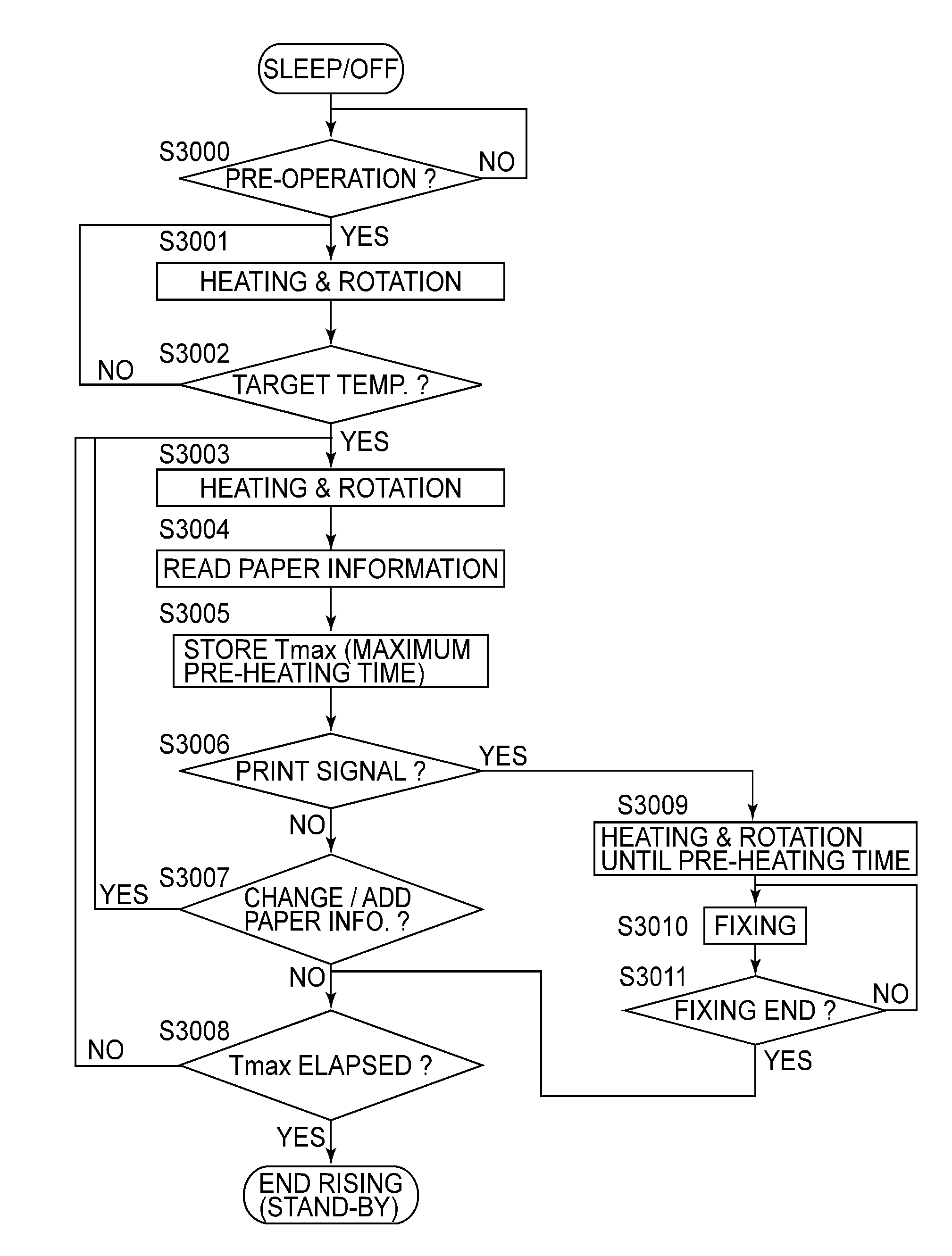
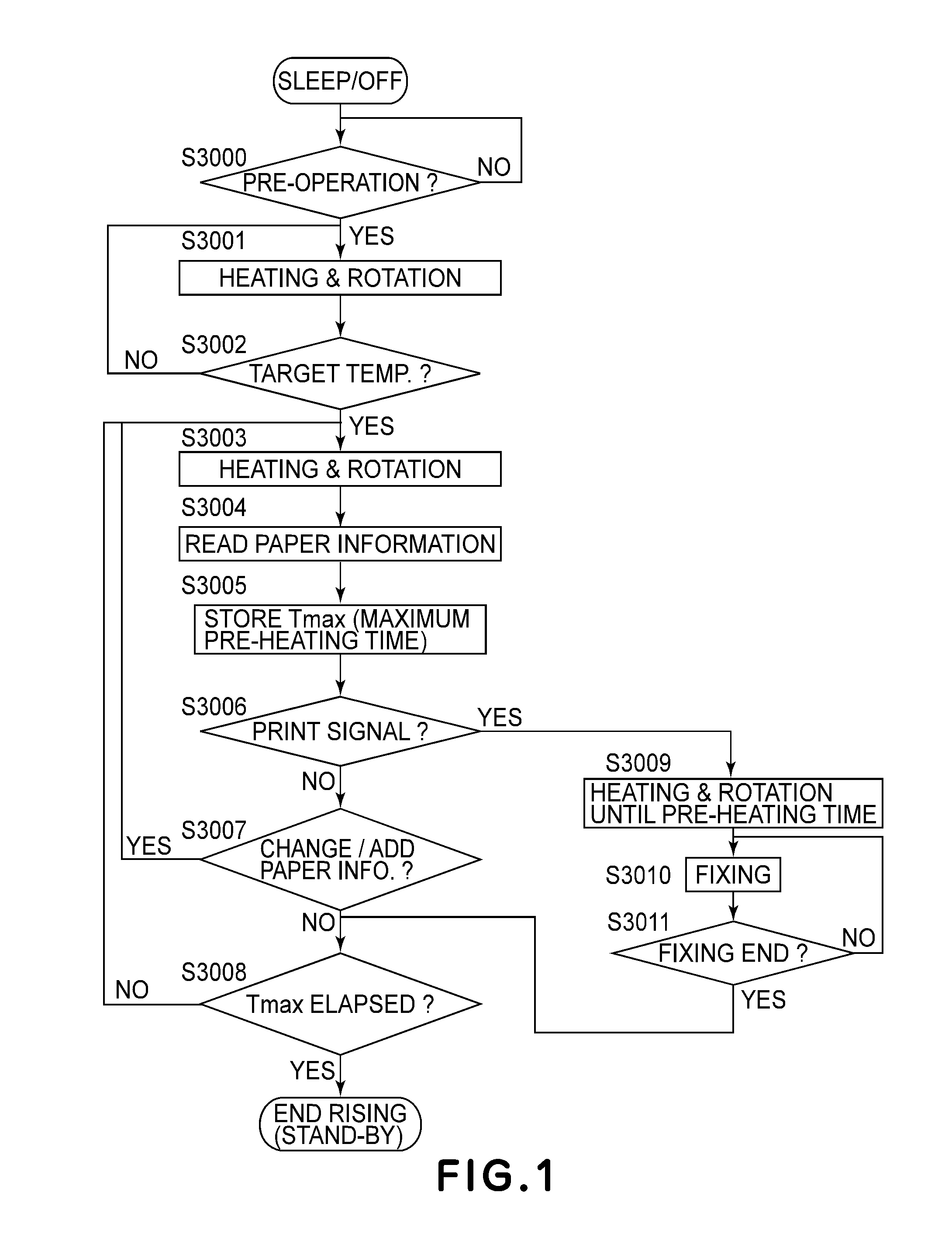
[0085]Second Embodiment is different from First Embodiment in that Tmax is set again on the basis of detected temperature information of the temperature detecting portion (FIG. 6). Control in this embodiment is identical in apparatus constitution and control for image formation and the like to the control in First Embodiment except that the flowchart of FIG. 1 is replaced with a flowchart of FIG. 8. In the following, the flowchart of FIG. 8 will be described, but steps in which the operations similar to those in First Embodiment are represented by the same reference symbols and will be omitted from description.

[0086]In this embodiment, for calculating Tmax, the necessary pre-heating time table is changed on the basis of detection information of a temperature and humidity detecting portion 801 provided at a periphery of the recording material cassettes 103, 104 and 105 disposed inside the main assembly of the image forming apparatus (S3100). Table 2 appearing later in a pre-heating t...

third embodiment

[0090]In First Embodiment, the pre-heating time is determined on the basis of the plurality of the pieces of the recording material basis weight information, but in this embodiment, different from First Embodiment, a longitudinal temperature difference is determined on the basis of the plurality of the pieces of the recording material basis weight information. In constituent elements and control in this embodiment, with respect to the same constituent elements as those in First Embodiment are represented by the same reference numerals or symbols and will be omitted from description. In the following, description will be made with reference to FIGS. 9 to 11.

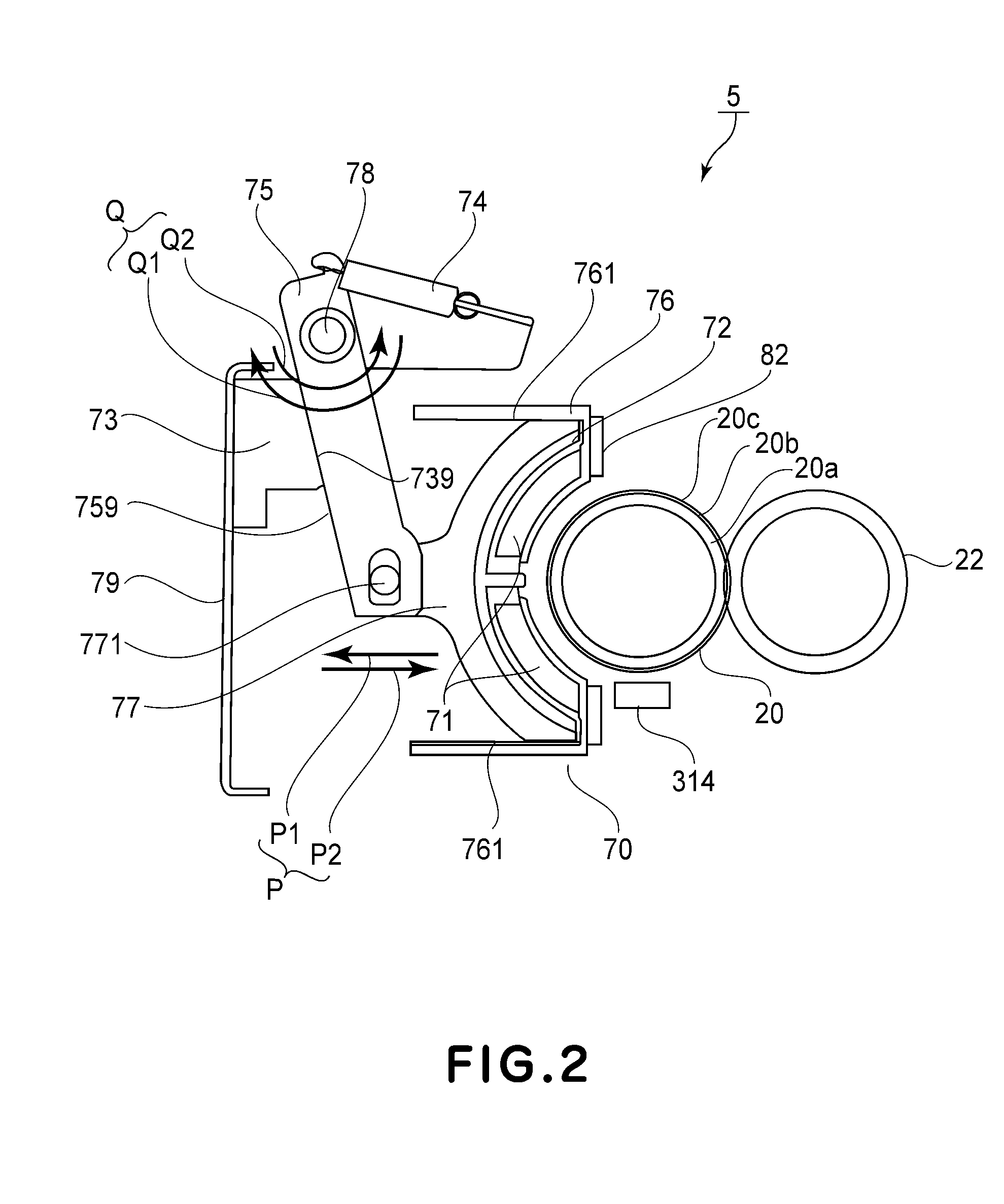
[0091]FIG. 9 is a sectional view of a fixing device 5 in this embodiment, and FIG. 10 is a schematic view of the fixing device 5, as seen from an arrow A direction of FIG. 9, from which the induction heating device 70 is removed. Further, FIG. 11 is a block diagram of an image forming apparatus 30 in this embodiment. In this embod...


PUM


Abstract

An image forming apparatus includes: a recording material accommodating portion configured to accommodate a recording material; an image forming portion configured to form a toner image on the recording material fed from the recording material accommodating portion; a fixing portion configured to heat-fix the toner image formed on the recording material by the image forming portion; a storing portion configured to store information corresponding to a type of the recording material accommodated in the recording material accommodating portion; a detecting portion configured to detect that a predetermined operation is performed by an operator before the image forming apparatus receives an image formation instruction; and an executing portion configured to execute a start-up process, when the detecting portion detects the predetermined operation performed by the operator, over a time depending on the information stored in the storing portion.

Description

FIELD OF THE INVENTION AND RELATED ART[0001]The present invention relates to an image forming apparatus for forming a toner image on a recording material. As this image forming apparatus, it is possible to cite an image forming apparatus, employing an electrophotographic process, an electrostatic recording process or the like, represented by, e.g., a copying machine, a printer, a facsimile machine, a multi-function machine having functions of these machines, or the like.[0002]In a conventional image forming apparatus of an electrophotographic type, a constitution in which an unfixed toner image is formed on the recording material by an image forming process mechanism is employed. Further, a fixing process for heat-fixing the unfixed toner image on the recording material by a fixing device incorporated in the image forming apparatus is performed.[0003]In such a fixing device, shortening of a start-up time (waiting time of an operator) until the fixing device is capable of performing ...

Claims


Application Information

Patent Timeline
IPC IPC(8): G03G15/20
CPCG06K15/005G03G15/205G03G15/2017G03G15/5091G03G15/2039
Inventor MATSUURA, DAIGO
Owner CANON KK
Learn More