Systems and methods for making and using segmented tip electrodes for leads of electrical stimulation systems

a technology of electrical stimulation system and segmented tip electrode, which is applied in the direction of head electrode, electrotherapy, therapy, etc., can solve problems such as unsatisfactory side effects, and achieve the effect of facilitating retention of pre-tip electrodes

Inactive Publication Date: 2015-02-12
BOSTON SCI NEUROMODULATION CORP
View PDF2 Cites 167 Cited by
  • Summary
  • Abstract
  • Description
  • Claims
  • Application Information

AI Technical Summary

Benefits of technology

[0006]In another embodiment, a method of making a stimulation lead includes disposing a pre-tip-electrode along a distal tip of a lead body. The pre-tip-electrode includes a pre-tip-electrode body having an outer surface, an inner surface opposite the outer surface, a proximal end, and a distal end. The pre-tip-electrode body includes a ring-shaped base portion disposed along the proximal end of the pre-tip-electrode body; and a plurality of circumferentially-spaced-apart segmented tip electrodes coupled to the ring-shaped base portion and extending distally therefrom. The segmented tip electrodes each curve inwardly as they extend distally from the ring-shaped base portion such that the pre-tip-electrode body forms a substantially dome-shaped structure. The plurality of circumferentially-spaced-apart segmented tip electrodes are coupled to a plurality of terminals disposed along a proximal end portion of the lead body. Non-conductive material is placed against the inner surfaces of the pre-tip-electrode body and between the circumferentially-spaced-apart segmented tip electrodes to facilitate retention of the pre-tip-electrode with the lead body.

Problems solved by technology

Consequently, undirected stimulation may result in unwanted stimulation of neighboring neural tissue, potentially resulting in undesired side effects.

Method used


Image

  • Systems and methods for making and using segmented tip electrodes for leads of electrical stimulation systems
  • Systems and methods for making and using segmented tip electrodes for leads of electrical stimulation systems
  • Systems and methods for making and using segmented tip electrodes for leads of electrical stimulation systems

Examples


Embodiment Construction

[0030]The present invention is directed to the area of implantable electrical stimulation systems and methods of making and using the systems. The present invention is also directed implantable electrical stimulation systems with leads having segmented tip electrodes, as well as methods of making and using the leads, segmented tip electrodes, and electrical stimulation systems.

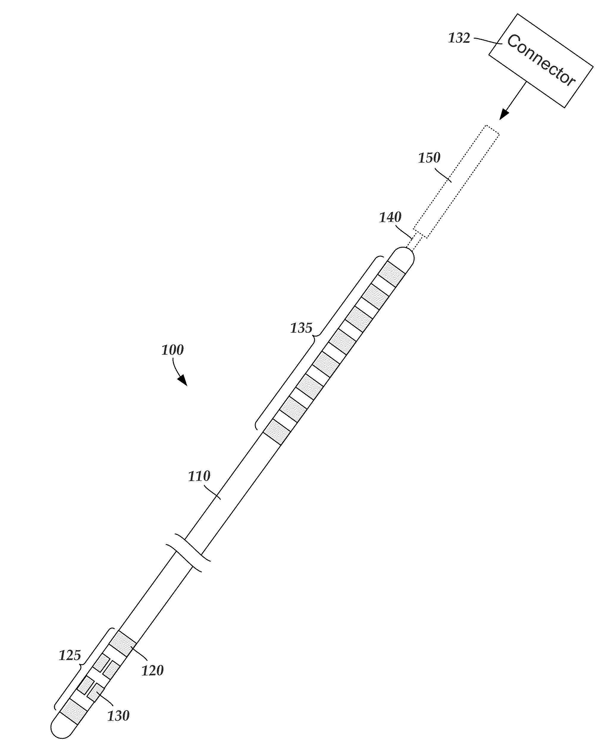
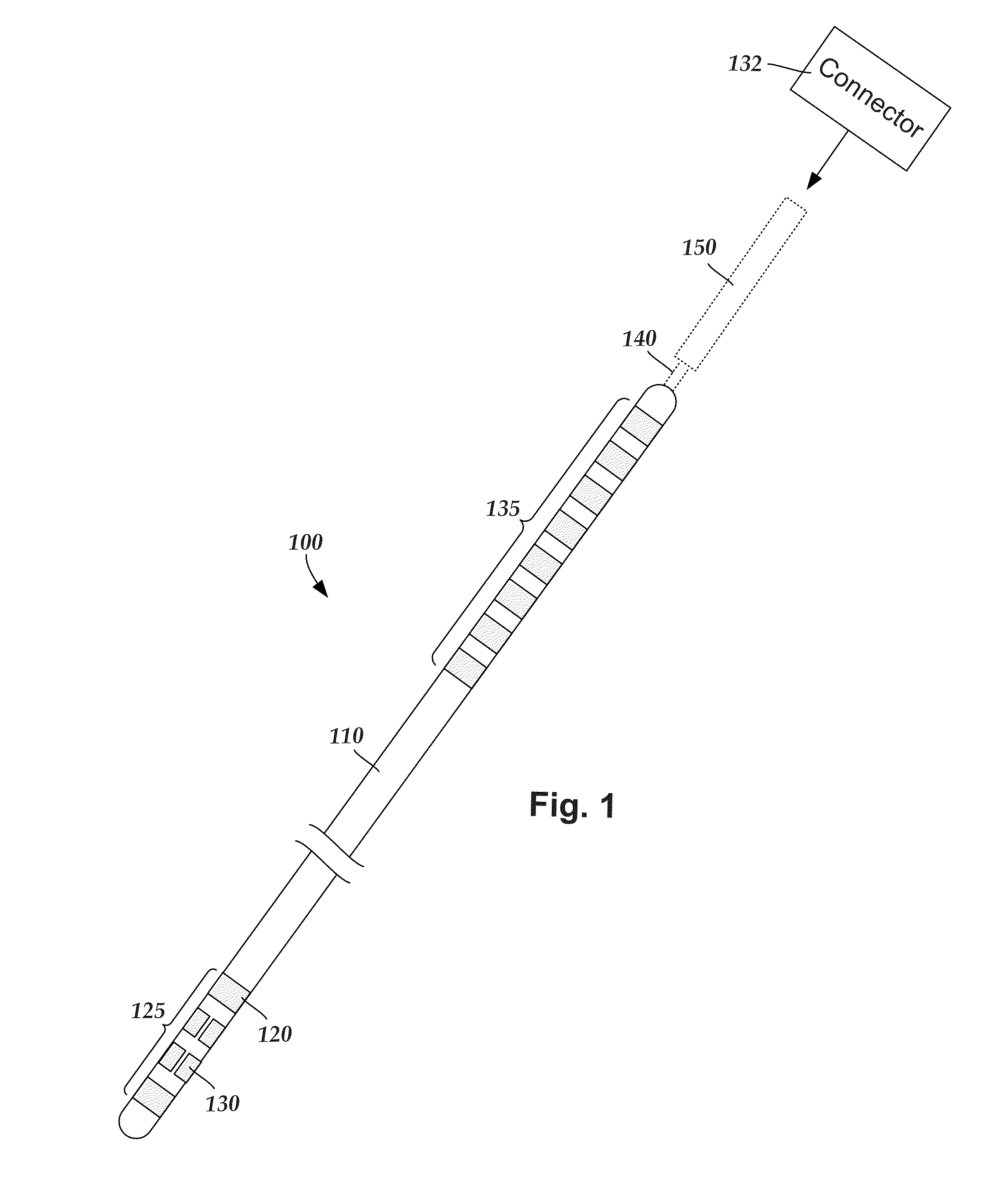
[0031]A lead for deep brain stimulation may include stimulation electrodes, recording electrodes, or a combination of both. At least some of the stimulation electrodes, recording electrodes, or both are provided in the form of segmented electrodes that extend only partially around the circumference of the lead. These segmented electrodes can be provided in sets of electrodes, with each set having electrodes radially distributed about the lead at a particular longitudinal position. For illustrative purposes, the leads are described herein relative to use for deep brain stimulation, but it will be understood tha...


PUM

PropertyMeasurementUnit
cross-sectional diameteraaaaaaaaaa
lengthaaaaaaaaaa

Abstract

An implantable electrical stimulation lead includes a lead body having a proximal end portion, a distal end portion, a distal tip, a longitudinal length, and a longitudinal surface. Segmented tip electrodes are disposed circumferentially about the distal tip of the lead body and are electrically-isolated from each other. Each segmented tip electrode has an inner surface and an opposing outer stimulating surface exposed along the longitudinal surface of the lead body. A portion of the lead body is disposed against the inner surfaces of each of the segmented tip electrodes and circumferentially between each of the segmented tip electrodes. A non-tip electrode is disposed along the distal end portion of the lead body proximal to the segmented tip electrodes. Terminals are disposed along the proximal end portion of the lead body. Conductors electrically couple the terminals to the segmented tip electrodes and to the non-tip electrode.

Description

CROSS-REFERENCE TO RELATED APPLICATIONS[0001]This application claims the benefit under 35 U.S.C. §119(e) of U.S. Provisional Patent Application Ser. No. 61 / 863,132, filed Aug. 7, 2013, which is incorporated herein by reference.FIELD[0002]The present invention is directed to the area of implantable electrical stimulation systems and methods of making and using the systems. The present invention is also directed implantable electrical stimulation systems with leads having segmented tip electrodes, as well as methods of making and using the leads, segmented tip electrodes, and electrical stimulation systems.BACKGROUND[0003]Electrical stimulation can be useful for treating a variety of conditions. Deep brain stimulation can be useful for treating, for example, Parkinson's disease, dystonia, essential tremor, chronic pain, Huntington's disease, levodopa-induced dyskinesias and rigidity, bradykinesia, epilepsy and seizures, eating disorders, and mood disorders. Typically, a lead with a st...

Claims


Application Information

Patent Timeline
Patent Type & Authority Applications(United States)
IPC IPC(8): A61N1/05A61N1/375
CPCA61N1/3752A61N1/0534Y10T29/49117
Inventor HOWARD, JOSHUA DALE
Owner BOSTON SCI NEUROMODULATION CORP
Why Eureka
Try Eureka