Filament Winding Device

a technology of winding device and filament, which is applied in the direction of filament handling, transportation and packaging, thin material processing, etc., can solve the problems of deterioration of production efficiency and production efficiency

Active Publication Date: 2015-02-19
MURATA MASCH LTD +1
View PDF4 Cites 4 Cited by
  • Summary
  • Abstract
  • Description
  • Claims
  • Application Information

AI Technical Summary

Benefits of technology

[0012]The present invention exerts effects described below.
[0013]According to the first aspect, with respect to the filament winding device according to the present embodiment, since the liner support device and the hoop winding device are arranged upon the trolley, the liner and the hoop winding device can be simultaneously transported by moving the trolley.
[0014]According to the second aspect, with respect to the filament winding device according to the present embodiment, since the at least two trolleys are placed on rails, the liner and the hoop winding device can be simultaneously exchanged by moving the respective trolleys.
[0015]According to the third aspect, with respect to the filament winding device according to the present embodiment, since the work space for carrying out exchanging work of the bobbin in which the fiber bundles have been wound and the liner is provided in the vicinity of the rails, the bobbin with few fiber bundles or the liner in which the fiber bundle has been already wound can be exchanged while carrying out the winding operation of a fiber bundle to a new liner.
[0016]According to the fourth aspect, with respect to the filament winding device according to the present embodiment, since the filament winding device includes the liner transfer device which is configured to be connected to / separated from the liner shaft, the trolley is movable in such a condition that the liner shaft is separated from the liner transfer device.
[0017]According to the fifth aspect, with respect to the filament winding device according to the present embodiment, when the liner shaft is supported by the liner support device, the liner transfer device is separated from the liner shaft. In such a condition, the liner can be conveyed while the liner is placed on the trolley. Also, when the liner transfer device is connected to the liner shaft, the liner support device is separated from the liner shaft. In such a condition, the liner can be transferred by the liner transfer device.

Problems solved by technology

However, when the fiber bundle winding operation is interrupted so as to exchange the bobbin, a considerable time is required until the restart of the fiber bundle winding operation, and thus there is a problem of deterioration of producing efficiency
However, when the exchanging work of the liner is carried out, a considerable time is required until the restart of the fiber bundle winding operation, and thus there is a problem of deterioration of producing efficiency.

Method used


Image

  • Filament Winding Device
  • Filament Winding Device
  • Filament Winding Device

Examples


Embodiment Construction

[0028]Next, an explanation will be given of embodiments of the present invention.

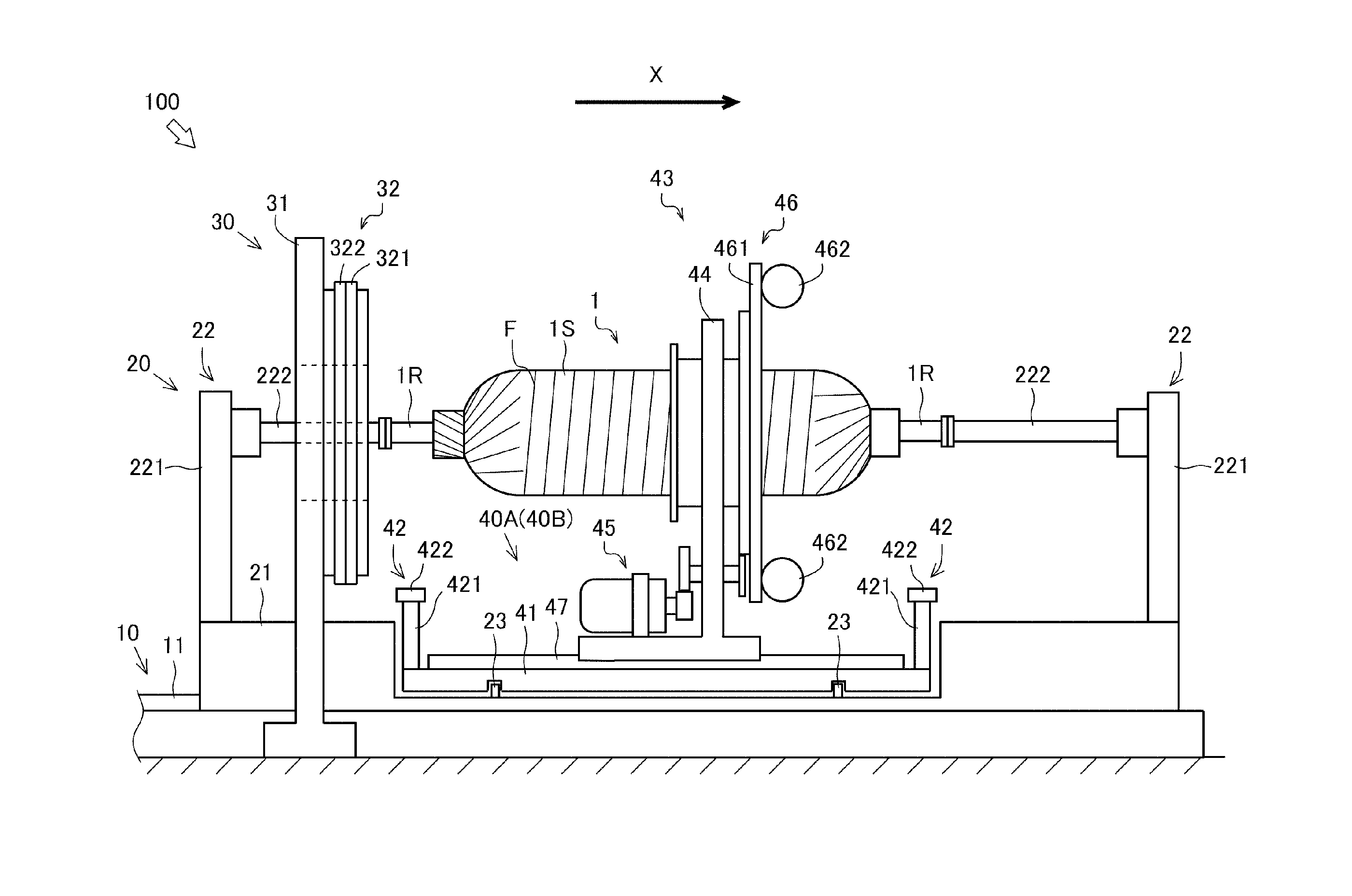
[0029]First of all, a brief explanation will be given of an overall configuration of a filament winding device 100 (hereinafter, “FW device 100”).

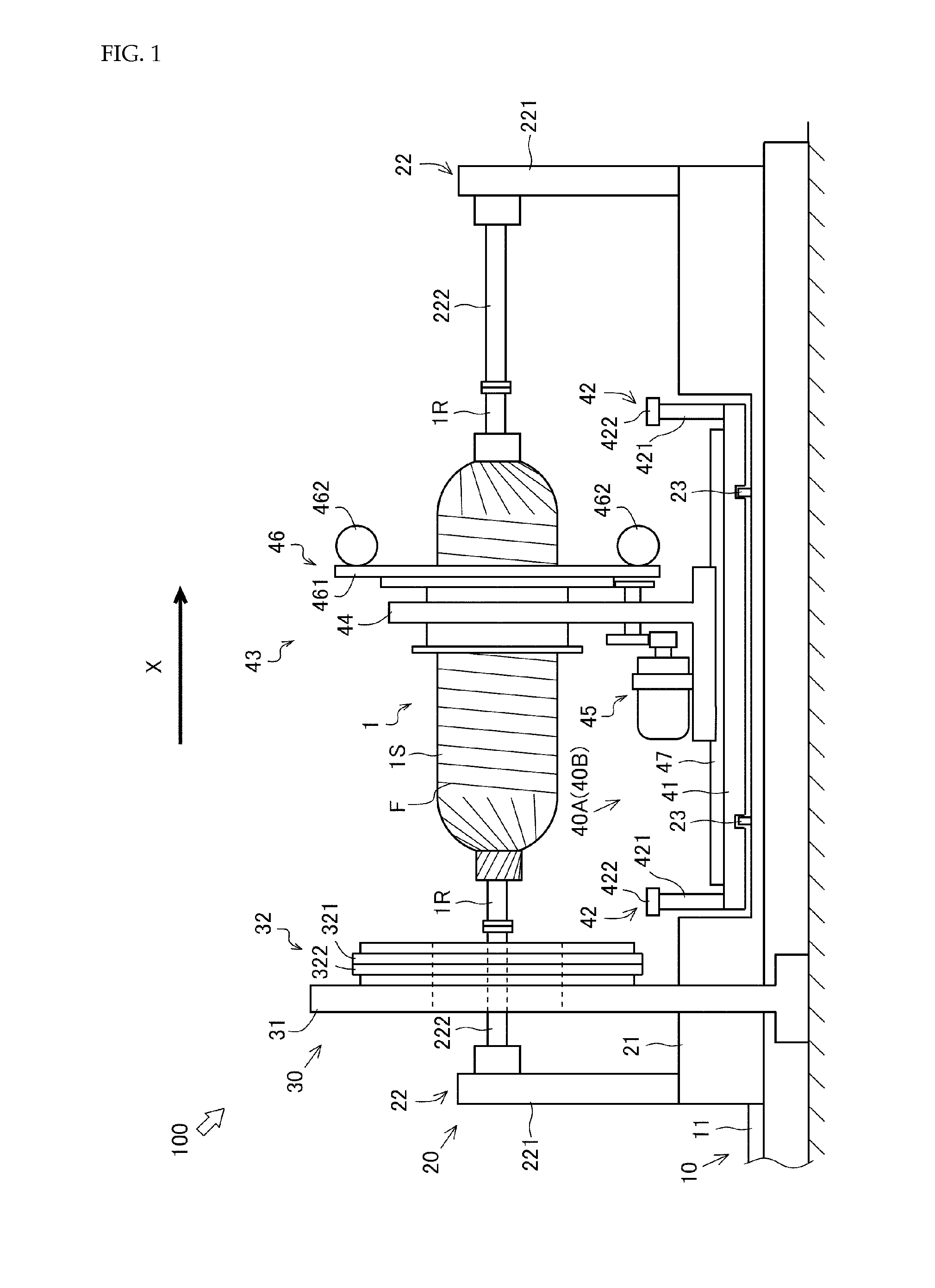
[0030]FIG. 1 is a side view illustrating the overall configuration of the FW device 100. An arrow X in the drawing indicates a transfer direction of a liner 1. The direction in parallel to the transfer direction of the liner 1 is regarded as the longitudinal direction of the FW device 100, and one direction of transferring the liner 1 is defined as the front side (right side in this drawing), and the other direction opposite thereto is defined as the rear side (left side in this drawing). The FW device 100 reciprocates the liner 1 in the longitudinal direction, whereby the front side and the rear side are defined depending on the transfer direction of the liner 1.

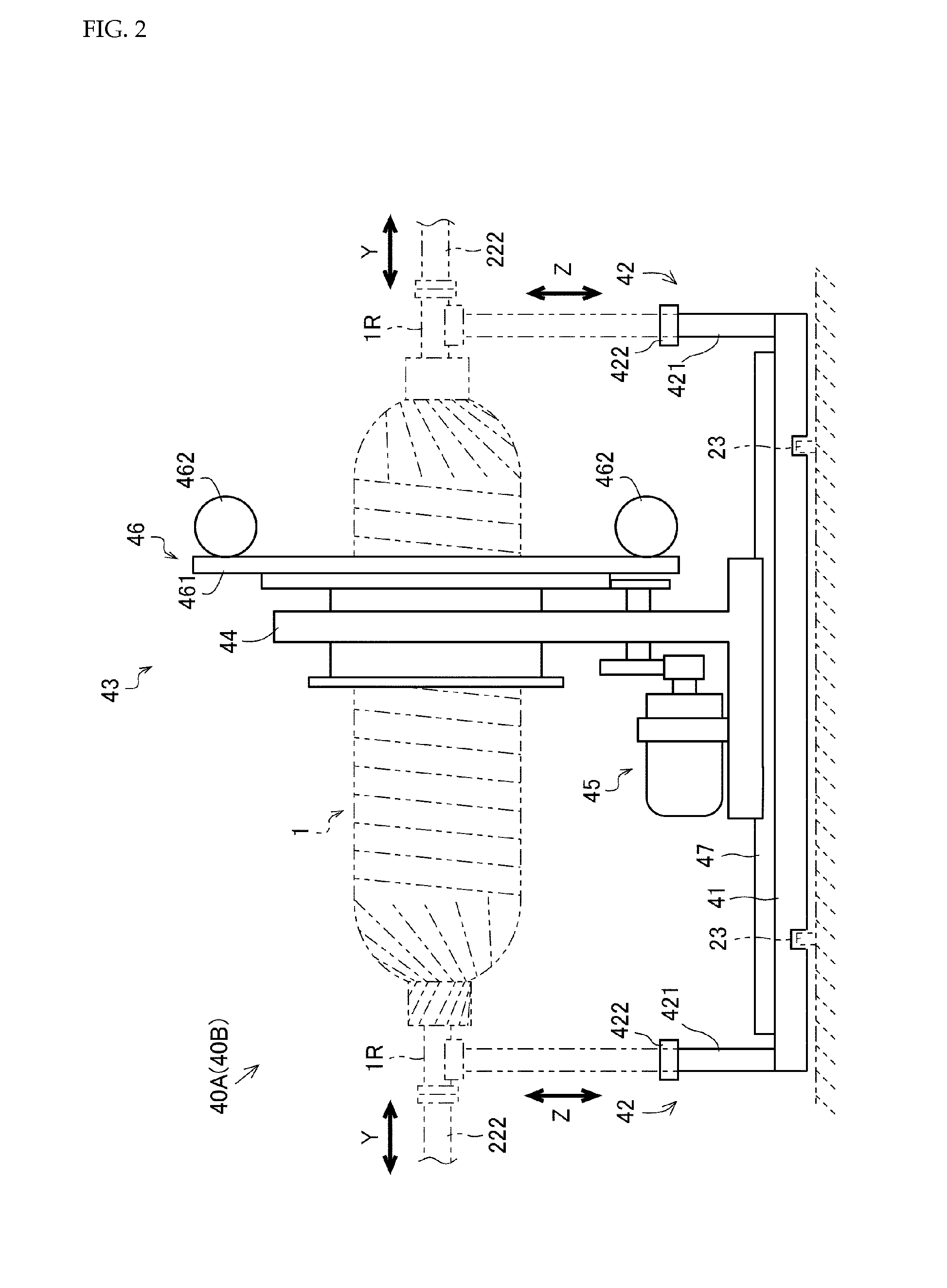
[0031]FIG. 2 is a side view illustrating a configuration of trolleys 40A, 40B. An arrow Y in the d...


PUM

PropertyMeasurementUnit
strengthaaaaaaaaaa
pressure resistanceaaaaaaaaaa
winding angleaaaaaaaaaa

Abstract

A filament winding device (100) comprising a liner support device (42) supporting a liner (1), and a hoop winding device (43) that winds a fiber bundle (F) on to the outer peripheral surface (1S) of the liner (1) by rotating centered around the liner (1). The filament winding device (100) is characterized by being capable of simultaneously transporting the liner (1) and the hoop winding device (43), by having the liner support device (42) and the hoop winding device (43) arranged upon a trolley (40A), and moving the trolley (40A).

Description

TECHNICAL FIELD[0001]The present invention relates to a technique of a filament winding device.BACKGROUND ART[0002]Conventionally, a filament winding device which winds a fiber bundle impregnated with resin on to the outer peripheral surface of a liner has been known. The filament winding device is provided with a hoop winding device that winds the fiber bundle on to the outer peripheral surface of the liner by rotating centered around the liner (for example, see Patent Literature 1).[0003]The hoop winding device is provided with a bobbin in which the fiber bundle has been wound, and the fiber bundle supplied from the bobbin is wound on to the liner by self-rotation of the hoop winding device. As such, with respect to the filament winding including the hoop winding device, when the fiber bundle wound on to the bobbin runs low, there is a need to interrupt the fiber bundle winding operation and exchange the bobbin. However, when the fiber bundle winding operation is interrupted so as...

Claims


Application Information

Patent Timeline
Patent Type & Authority Applications(United States)
IPC IPC(8): B65H67/06B29C53/80B29C53/60
CPCB65H67/068B29C53/8016B29C53/602
Inventor TANIGAWA, MOTOHIRONAKAMURA, DAIGOROUOZUMI, TADASHIHATTA, KEN
Owner MURATA MASCH LTD
Why Eureka
Try Eureka