Tuning-fork resonator with grooves on principal surfaces

a resonator and principal surface technology, applied in the direction of piezoelectric/electrostrictive/magnetostrictive devices, oscillators, piezoelectric/electrostrictive device details, etc., can solve the problem of generating loss of vibration energy, significantly reducing stiffness of the resonating arm part, and insufficient suppression of heat transfer from the contracting surface to the expanding surfa

Inactive Publication Date: 2011-04-07
SEIKO EPSON CORP
View PDF7 Cites 4 Cited by
  • Summary
  • Abstract
  • Description
  • Claims
  • Application Information

AI Technical Summary

Benefits of technology

[0054]According to the configuration, the electronic apparatus includes the resonator element according to any one of the application examples 1 to 5, and thus, an electronic apparatus that exerts the effect described in any one of the application examples 1 to 5 may be provided.

Problems solved by technology

However, if a through hole is formed in the vibrating part (hereinafter, referred to as “resonating arm part”) of the piezoelectric resonator element as in JP-UM-A-2-32229, there is a problem that the stiffness of the resonating arm part is significantly reduced.
Further, if the piezoelectric resonator element is provided with an H-shaped groove (hereinafter, referred to as “groove part”) in the resonating arm part as in JP-UM-A-2-32229, the suppression of the heat transfer from the contracting surface to the expanding surface is insufficient and there is room for improvement in suppression of the reduction of the Q factor caused by thermoelastic loss.
As a result, in the piezoelectric resonator element, the vibration direction of the flexing vibration is no longer along the specified vibration direction, and the loss of vibration energy is generated and the efficiency of the flexing vibration becomes lower.
As a result, in the resonator element, the vibration direction of the flexing vibration is no longer along the specified vibration direction, and the loss of vibration energy is generated and the efficiency of the flexing vibration becomes lower.

Method used


Image

  • Tuning-fork resonator with grooves on principal surfaces
  • Tuning-fork resonator with grooves on principal surfaces
  • Tuning-fork resonator with grooves on principal surfaces

Examples


first embodiment

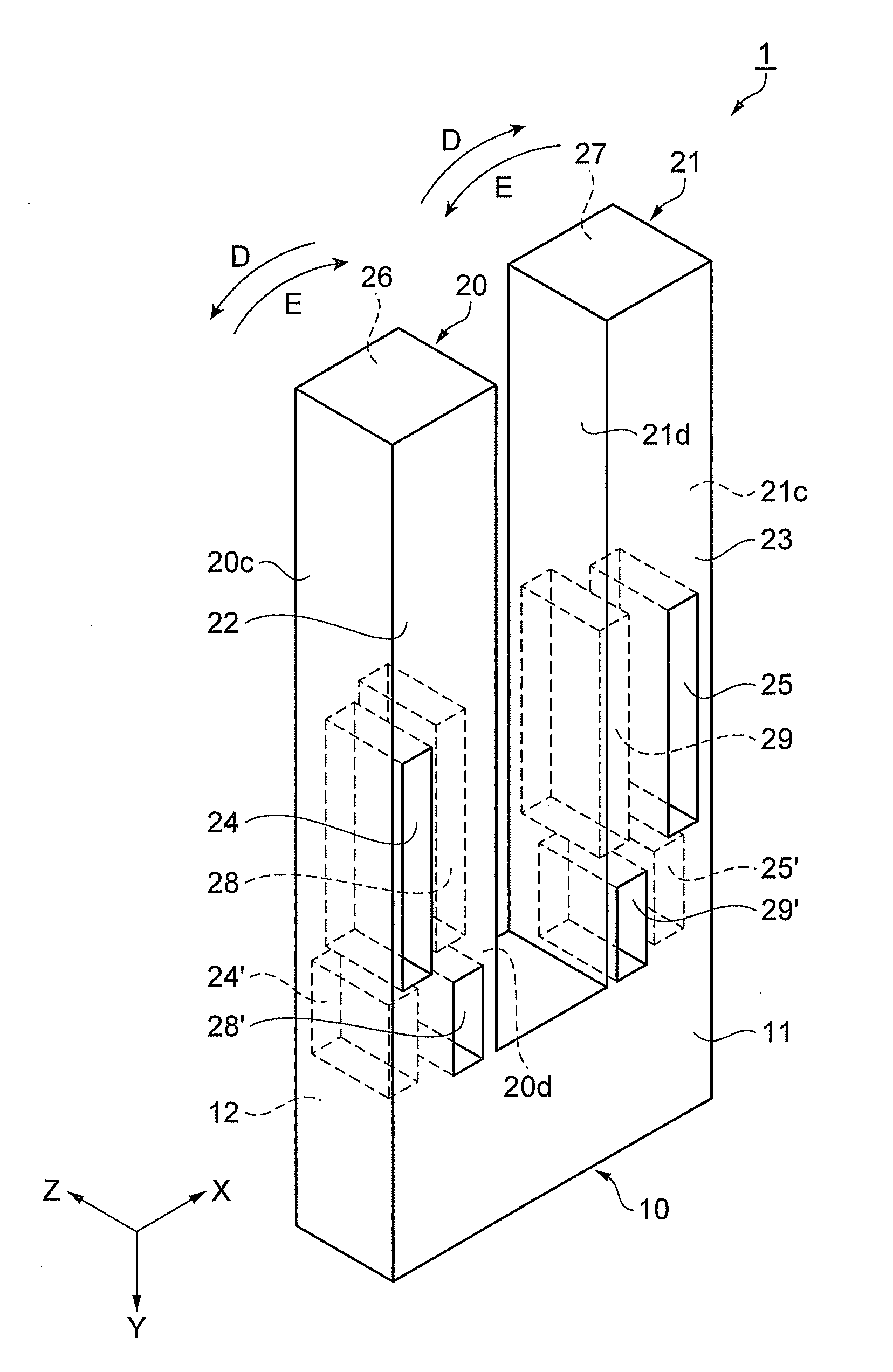
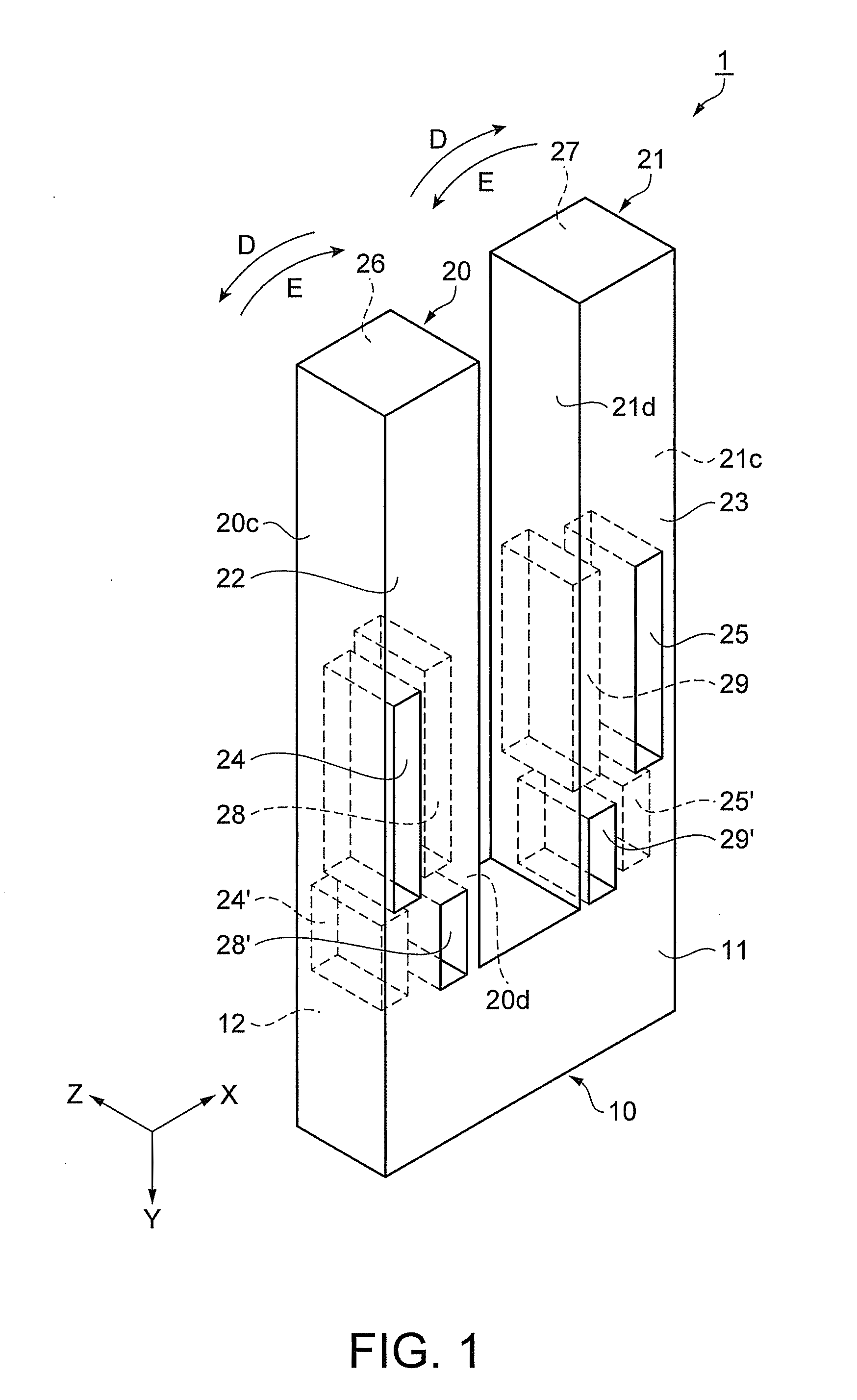
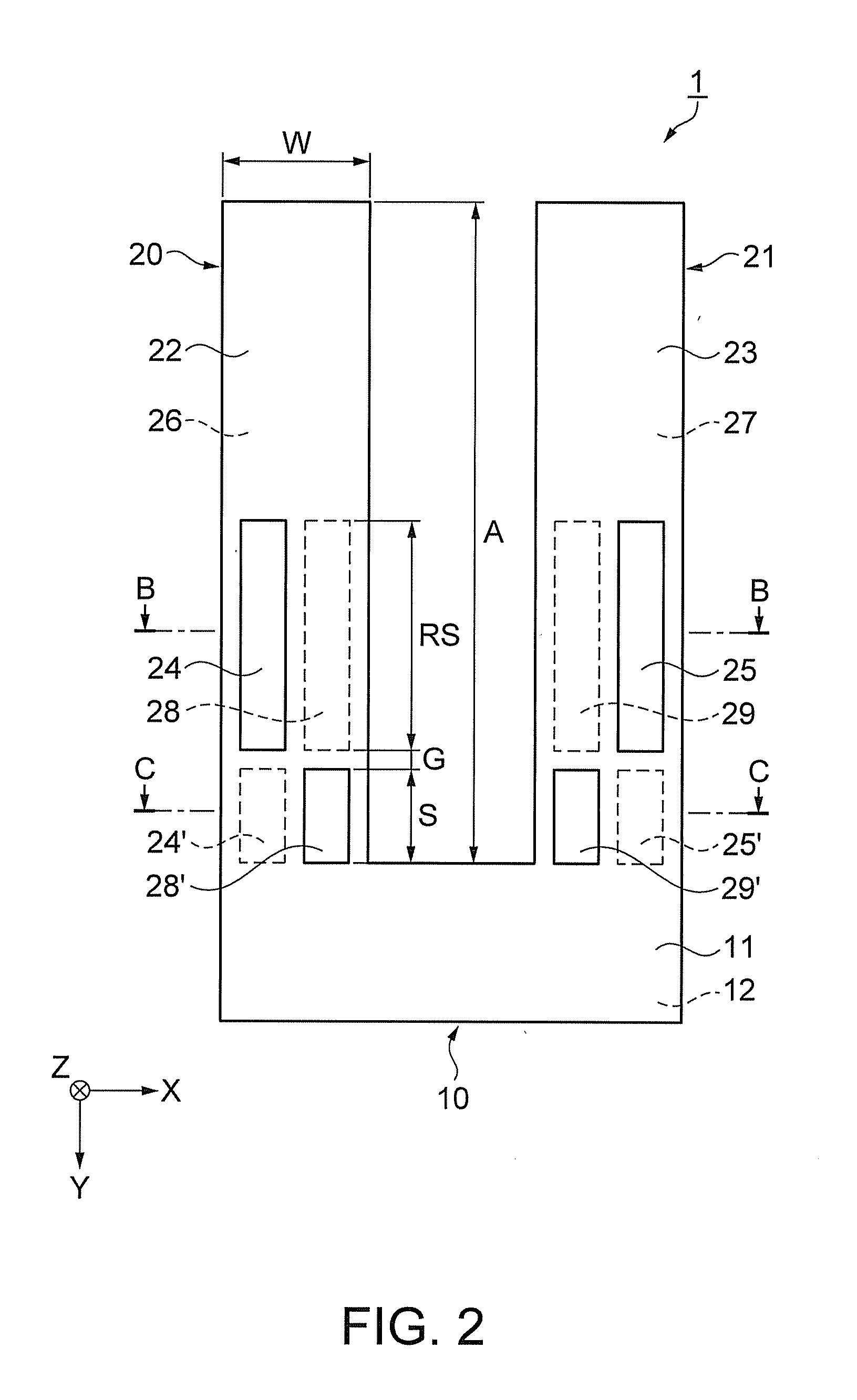
[0071]FIG. 1 is a schematic perspective view showing an outline configuration of a quartz resonator element of the first embodiment. FIG. 2 is a schematic plan view of FIG. 1. FIGS. 3A and 3B are schematic sectional views of FIG. 2, and FIG. 3A is a sectional view along B-B line of FIG. 2 and wiring diagram and FIG. 3B is a sectional view along C-C line of FIG. 2 and wiring diagram. Note that, in FIGS. 1 and 2, electrodes and the like are omitted for convenience.

[0072]As shown in FIGS. 1 and 2, a quartz resonator element 1 includes a base part 10, and a pair of resonating arm parts 20, 21 extending from the base part 10 in a first direction (Y-axis direction) and performs flexing vibration.

[0073]The quartz resonator element 1 forms a tuning fork with the base part 10 and the pair of resonating arm parts 20, 21.

[0074]The pair of resonating arm parts 20, 21 are formed in rectangular column shapes, and extend in parallel with each other from one end side of the base part 10 in the Y-ax...

modified example

[0148]As below, a modified example of the quartz resonator element of the first embodiment will be explained.

[0149]FIG. 7 is a schematic plan view showing a quartz resonator element of a modified example of the first embodiment. The same signs are assigned to the common parts with the first embodiment and their explanation will be omitted, and the parts different from those of the first embodiment will be explained mainly.

[0150]As shown in FIG. 7, in a quartz resonator element 101, the arrangement of the first groove part 25 and the second groove part 29 and the third groove part 25′, and the fourth groove part 29′ in a resonating arm part 121 is reversed compared to the arrange of those of the resonating arm part 21 of the quartz resonator element 1 in the embodiment. In other words, in the quartz resonator element 101, the arrangement of the respective groove parts is the same in the resonating arm part 20 and the resonating arm part 121.

[0151]The quartz resonator element 101 may ...

second embodiment

[0153]As below, a quartz resonator as a resonator of the second embodiment will be explained as an example.

[0154]FIG. 8 is a schematic plan view showing an outline configuration of a quartz resonator of the second embodiment. FIG. 9 is a schematic sectional view along J-J line of FIG. 8. In FIG. 8, a lid body is omitted for convenience.

[0155]Further, the same signs are assigned to the common parts with the first embodiment and their explanation will be omitted.

[0156]The quartz resonator 80 of the second embodiment is a quartz resonator using the quartz resonator element of the first embodiment or the modified example of the first embodiment. Here, the explanation will be made using the quartz resonator element 1 of the first embodiment.

[0157]As shown in FIGS. 8, 9, the quartz resonator 80 houses the quartz resonator element 1 within a package 51. Specifically, the quartz resonator 80 houses the quartz resonator element 1 in an internal space S of the package 51 including a first sub...


PUM


Abstract

A resonator element includes: a base part; and a resonating arm part that extends from the base part in a first direction and performs flexing vibration, wherein the resonating arm part has one principal surface and the other principal surface opposed to the one principal surface, a first groove part provided along the first direction of the resonating arm part on the one principal surface, a second groove part provided in juxtaposition with the first groove part in a second direction orthogonal to the first direction in a plan view on the other principal surface, a third groove part provided in juxtaposition with the first groove part in the first direction in the plan view and provided nearer the base part side than the first groove on the other principal surface, and a fourth groove part provided in juxtaposition with the second groove part in the first direction in the plan view and provided nearer the base part side than the second groove on the one principal surface, and wherein a sum of a depth of the first groove part and a depth of the second groove part and a sum of a depth of the third groove part and a depth of the fourth groove part are larger than a distance between the one principal surface and the other principal surface.

Description

BACKGROUND[0001]1. Technical Field[0002]The present invention relates to a resonator element, a resonator, an oscillator, and an electronic apparatus.[0003]2. Related Art[0004]In related art, it is known that, as a piezoelectric resonator element as an example of a resonator element is made smaller, the Q factor becomes smaller and vibration is hindered.[0005]Specifically, in the piezoelectric resonator element, with elastic deformation due to flexing vibration, the temperature of the contracting surface rises and the temperature of the expanding surface falls, and a temperature difference is produced within. Thereby, in the piezoelectric resonator element, vibration called relaxation oscillation occurs in inverse proportion to a required time (relaxation time) until the temperature difference is eliminated (temperature equilibration) by thermal conduction (heat transfer).[0006]As the piezoelectric resonator element is made smaller, the frequency of the relaxation oscillation and th...

Claims


Application Information

Patent Timeline
Patent Type & Authority Applications(United States)
IPC IPC(8): H01L41/04H03B5/32
CPCH03H9/0547H03H9/215H03H9/1021
Inventor FURUHATA, MAKOTOYAMAZAKI, TAKASHI
Owner SEIKO EPSON CORP
Why Eureka
Try Eureka