Switch unit and game machine

a technology of switch unit and key, which is applied in the direction of emergency actuators, electrical devices, legends, etc., can solve the problems of lack of stereoscopic effect, flat unit with display portion provided on the rear surface of the key, and inability to give intuitive operation feeling

Inactive Publication Date: 2014-10-30
ORMON CORP
View PDF1 Cites 5 Cited by
  • Summary
  • Abstract
  • Description
  • Claims
  • Application Information

AI Technical Summary

Benefits of technology

[0021]According to one or more embodiments of the present invention, in a switch unit where a display portion is provided on the rear surface of a key, it is possible to give a stereoscopic effect, and the combination between this technique of making the switch unit look stereoscopic and a technique of floating an image of the display portion being on the rear surface of the key further exerts the effect of making the image look as if displayed on the operation surface of the key.

Problems solved by technology

In the above conventional configuration, however, the player just touches the screen, and thus cannot be given an intuitive operational feeling, as compared with a push-button system.
However, the switch unit with the display portion provided on the rear surface of the key is flat and lacks a stereoscopic effect as compared with the conventional push-button system.

Method used


Image

  • Switch unit and game machine
  • Switch unit and game machine
  • Switch unit and game machine

Examples


first embodiment

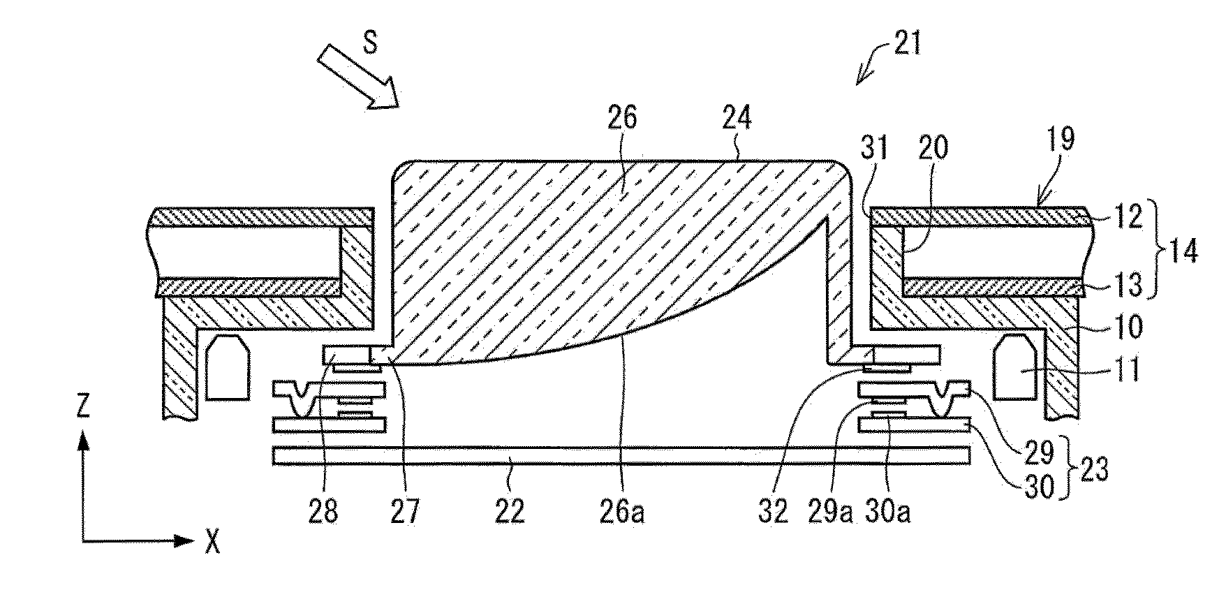
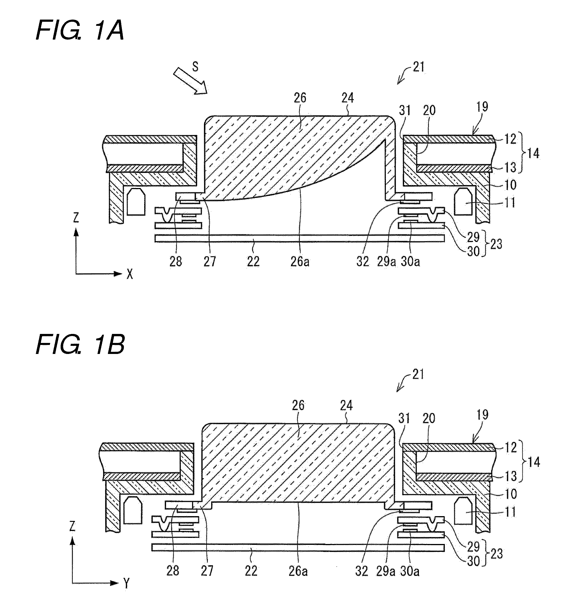
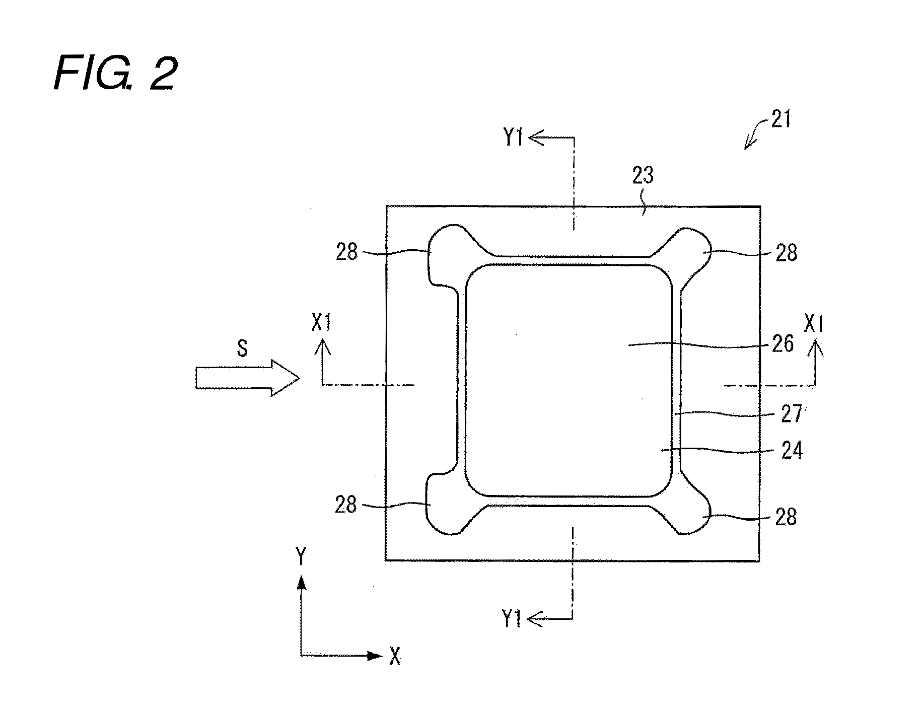
[0037]Hereinafter, a switch unit 21 according to a first embodiment of the present invention will be described with reference to FIGS. 1A to 8. FIGS. 1A and 1B are both sectional views of the switch unit 21 of the first embodiment. More specifically, FIG. 1A is a sectional view along a line X1-X1 of FIG. 2, and FIG. 1B is a sectional view along a line Y1-Y1 of FIG. 2. FIG. 2 is a plan view of the switch unit 21 of the first embodiment. However, in FIG. 2, an operation key cover denoted by numeral 19 in FIGS. 1A-B is omitted. It is to be noted that directions “top”, “bottom”, “left” and “right” used hereinafter are one merely to show directions on the drawings, and are not intended to restrict a posture of the switch unit when it is installed.

[0038]As shown in FIGS. 1A and 1B, the switch unit 21 is formed by superimposing a sheet switch 23 on an image display portion 22, placing an operation key 24 thereon, and further superimposing the operation key cover 19. The image display porti...

second embodiment

[0062]A second embodiment of the present invention will be described using FIGS. 9 and 10. It is to be noted that for convenience of description, members having similar functions as in the first embodiment are provided with the same reference number and a description thereof will be omitted. FIGS. 9A and 9B are both sectional views of a switch unit 21A of the second embodiment. More specifically, FIG. 9A is a sectional view corresponding to FIG. 1A, and FIG. 9B is a sectional view corresponding to FIG. 1B.

[0063]A difference between the switch unit 21A of the second embodiment and the switch unit 21 of the first embodiment (cf. FIG. 1A-B) lies in a structure of the opposing-mirror portion provided in the operation key cover 19. The half-mirror 12 and the mirror 13 are disposed as spaced from each other in the opposing-mirror portion 14, whereas the half-mirror 12 and the mirror 13 are separated from each other via a transparent member 16 in an opposing-mirror portion 17. That is, lig...

third embodiment

[0066]A switch unit according to one or more embodiments of the present invention can be used as a switch panel for a variety of game machines, industrial appliances, consumer appliances and the like. With reference to a third embodiment, a slot machine (game machine) provided with the switch unit according to one or more embodiments of the present invention will be described below.

[0067]FIG. 11 is a general perspective view of a slot machine 61 provided with a switch unit 101. In the slot machine 61, a reel portion 65 is provided in the central portion of the front surface facing a player (operator). The reel portion 65 is provided with a plurality of reels (not shown) where a plurality of kinds of symbols are displayed. A rotation of the plurality of reels is started by the player operating a reel rotation button 64 provided below the reel portion 65, and the rotation is automatically stopped by control of the appliance. When the reels are stopped, a combination is decided based o...


PUM


Abstract

A switch unit has an operation key, a cover member having an opening corresponding to the operation key, and a light emitting device disposed on a rear surface side of the cover member that makes the periphery of the operation key luminous by irradiation with light from a light emitting portion disposed on the periphery of the operation key. A top surface side of the operation key is inserted from the rear surface side of the cover member into the opening. An opposing-mirror portion is disposed on the cover member on at least a peripheral part of the operation key. The opposing-mirror portion has a half-mirror portion and a mirror portion spaced apart from the half-mirror portion with a space therebetween. The half-mirror portion is disposed above the mirror portion. The light emitting portion of the light emitting device faces the space between the half-mirror portion and the mirror portion.

Description

BACKGROUND[0001]1. Field[0002]The present invention relates to a switch unit, and especially relates to a switch unit provided with a display portion on the rear surface of a key, and a game machine loaded with the switch unit.[0003]2. Related Art[0004]In a slot machine being a kind of game machine, a plurality of reels displayed with a plurality of kinds symbols are spun, and when the reels are stopped, a combination is decided based on how symbols displayed in a window are aligned, or on the aligned symbols. A prize is given in accordance with the decided combination and the number of bets. A rotation of the reels is started by operation of a rotation-starting push button or lever provided on the slot machine. The reels are stopped automatically by control of an appliance as to a slot machine installed in a casino or the like.[0005]Incidentally, a recreation facility such as a casino is installed not only with slot machines manufactured by a single game machine manufacturer, but a...

Claims


Application Information

Patent Timeline
Patent Type & Authority Applications(United States)
IPC IPC(8): H01H13/02
CPCH01H13/023H01H13/83H01H2219/06H01H2219/062H01H2219/066H01H2221/07
Inventor KIMURA, MASATAKASUGIYAMA, HIROAKITAKAGI, YOSHIHIKOOSUMI, YOSHIMASA
Owner ORMON CORP
Why Eureka
Try Eureka