Projector for projecting visible and non-visible images

a projector and visible and non-visible technology, applied in the field of projectors for projecting visible and non-visible images, can solve the problem that projectors are not conventionally used to project images

Active Publication Date: 2015-02-19
MEP TECH
View PDF5 Cites 8 Cited by
  • Summary
  • Abstract
  • Description
  • Claims
  • Application Information

AI Technical Summary

Problems solved by technology

Projectors are not conventionally used to pr

Method used


Image

  • Projector for projecting visible and non-visible images
  • Projector for projecting visible and non-visible images
  • Projector for projecting visible and non-visible images

Examples


first physical embodiment

[0044]FIG. 5 illustrates a first physical embodiment 500 in which the projection system 100 is a projector 501 mounted to a ceiling 502 using mechanical mounts 507. Here, the projector projects an image 506 onto a vertical wall surface 504. A planar light emitter 503 emits co-planar infra-red light planes, and based on reflections, provides capture depth information to the projector 501 (which depth information may supplement depth information captured within the projector 501 via its own optics). For instance, the planar light emitter 503 send electrical signals over wiring 505, although wireless embodiments are also possible.

second physical embodiment

[0045]FIGS. 6A and 6B illustrates a second physical embodiment 600 in which the projection system is incorporated into a cam light. FIG. 6A illustrates a side view of the cam light system 600. The cam light system 600 includes the cam light 601 in which the projection system 100 is housed. The cam light 601 includes an exposed portion 602 that faces downward into the interior of the room whilst the remainder is generally hidden from view above the ceiling 603. A mounting plate 604 and mounting bolts 605 assist in mounting the cam light 601 within the ceiling 603. A power source 606 supplies power to the cam light 601.

[0046]FIG. 6B illustrates a bottom view, looking up, of the exposed portion 602 of the cam light 601. A visible light projector 610 emits light downward onto a horizontal surface below the cam light 600 (such as a table or countertop). When not projecting images, the visible light projector 610 may simply emit visible light to irradiate that portion of the room, and fun...


PUM


Abstract

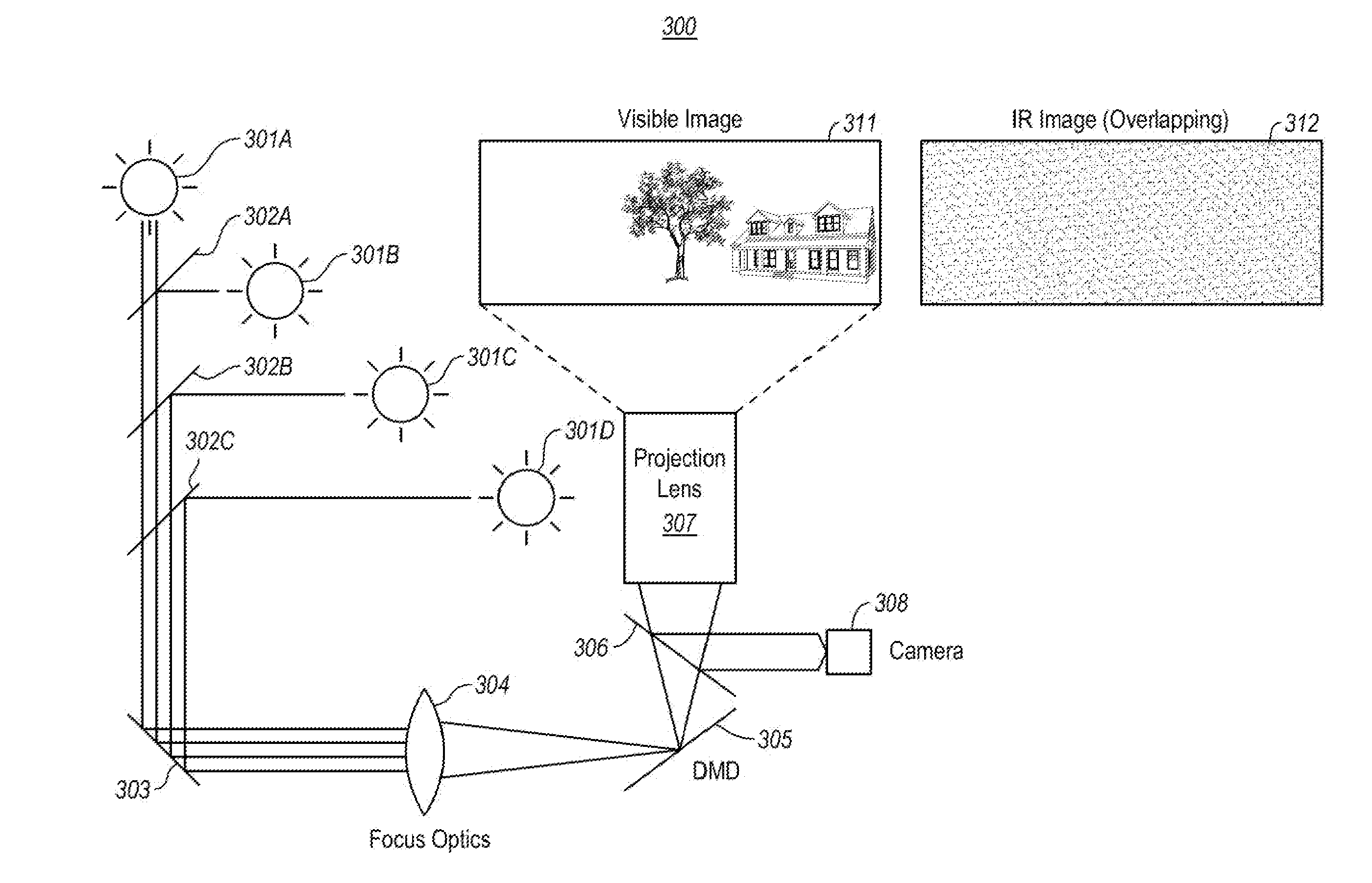
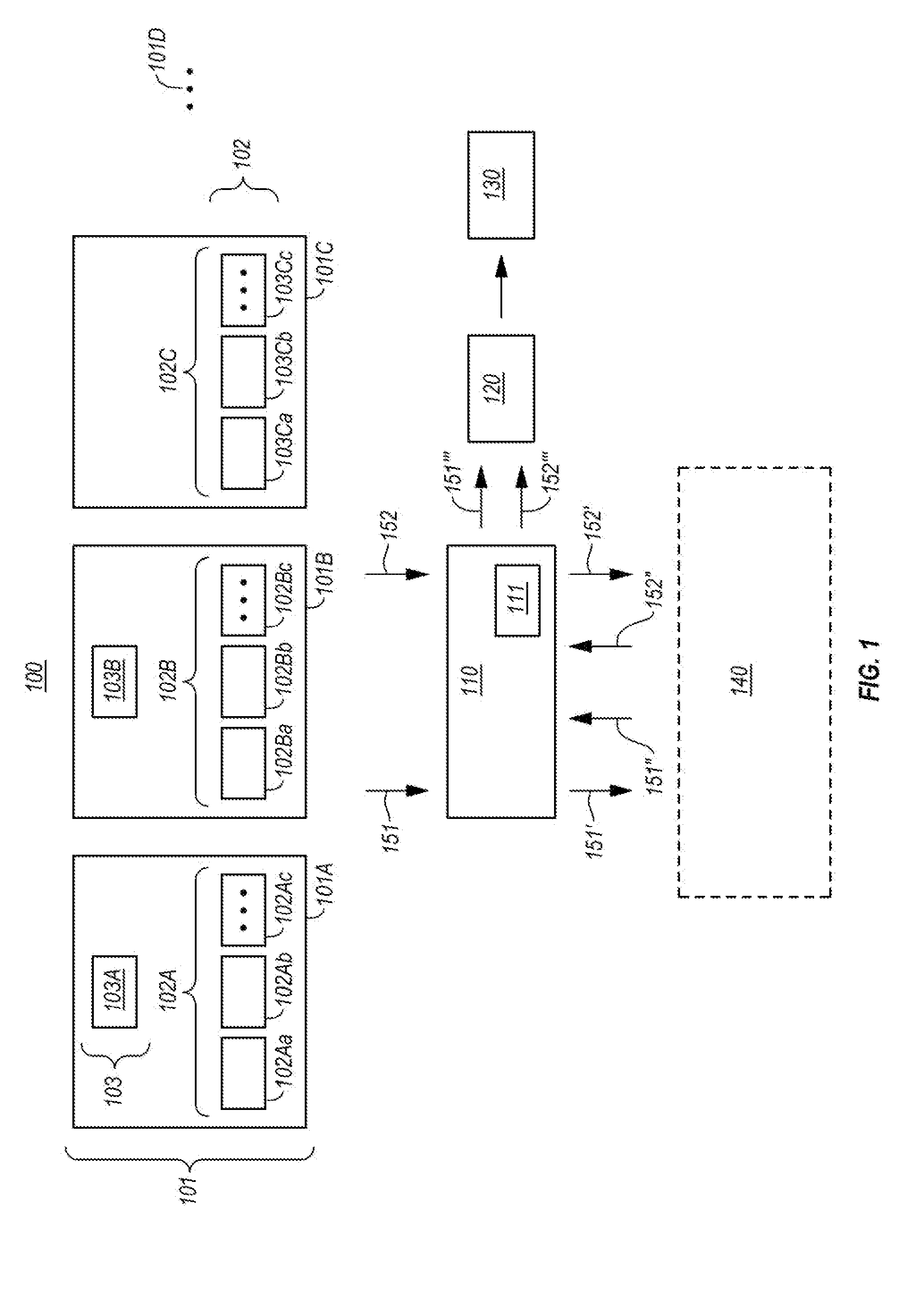
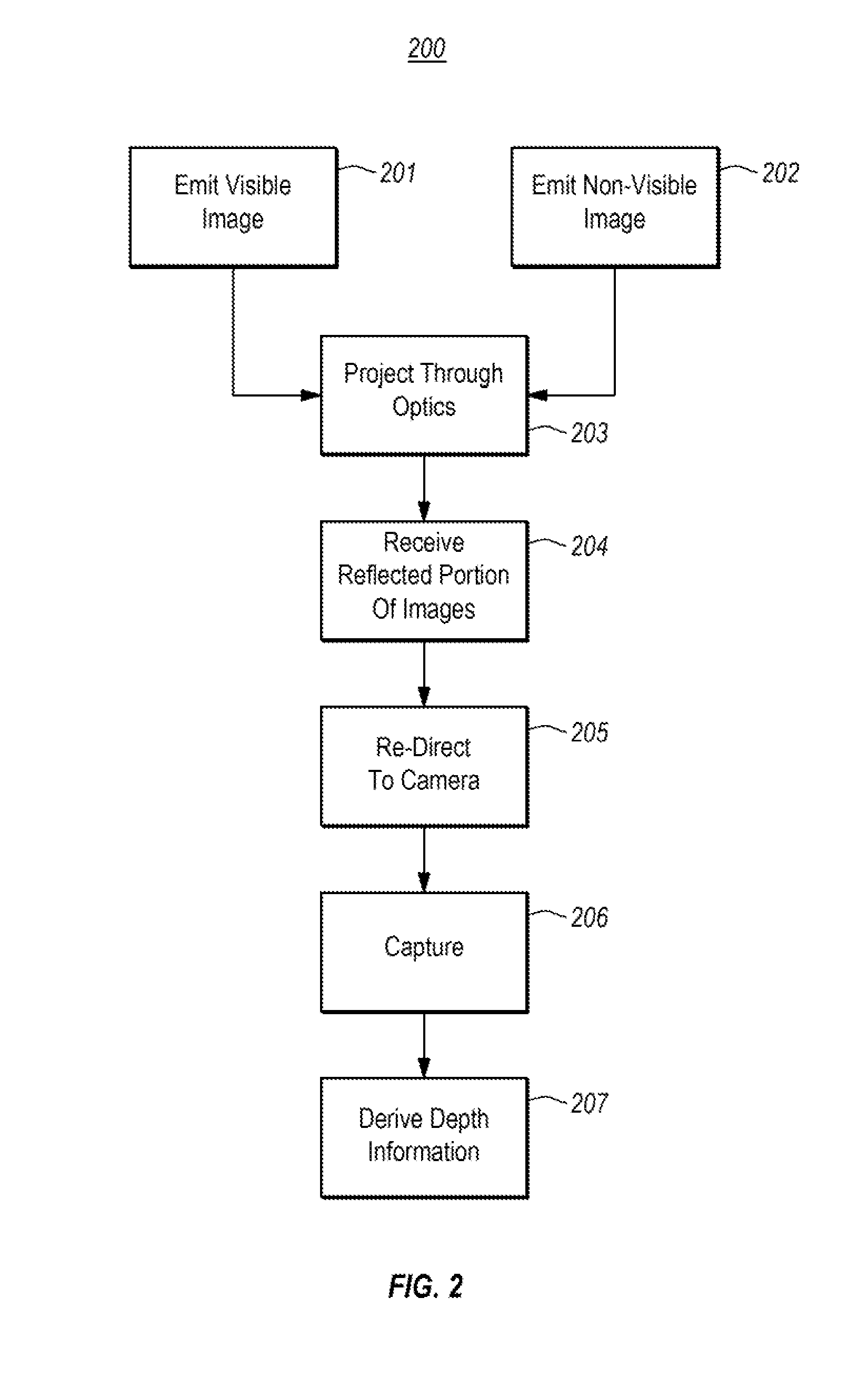
A projector that projects a visible image as well as a non-visible image. The non-visible image might be used for any purpose, but an example is in order to provide depth information regarding physical item(s) interacting with the projected visible image. The projector includes multiple projecting units (e.g., one for each pixel to be displayed), each including light-emitting elements configured to emit light in the visible spectrum. Some or all of those projecting units might also include an emitting element for emitting light in the non-visible spectrum so as to collectively emit a non-visible image. Optics may be positioned to project the visible image and the non-visible image. A depth sensing module detects depth of surfaces within the scope of the non-visible image using a reflected portion of the non-visible image.

Description

BACKGROUND[0001]Projectors are conventionally designed to project a visible image in which the projected light has frequencies within the visible spectrum. For instance, conventional projectors are capable of projecting an image composed of multiple pixels, each emitted by a distinct pixel unit. For each pixel unit, the projector includes multiple Light Emitting Diodes (LEDs). For instance, a pixel unit typically might include a red LED, a green LED, and a blue LED. The projected image passes through optics in a manner that the visible image is then focused on a surface at a distance from the projector. Projectors are not conventionally used to project images outside of the visible spectrum.BRIEF SUMMARY[0002]Embodiments described herein relate to a projector that projects a visible image as well as a non-visible image. The non-visible image might be used for any purpose, but an example is to provide depth information regarding physical item(s) interacting with the projected visible...

Claims


Application Information

Patent Timeline
IPC IPC(8): G03B21/14
CPCG03B21/142G03B17/54G03B33/12G06F3/0425H04N9/3164H04N9/3179H04N9/3194H04N13/271
Inventor MEALING, DONALD ROYDAVIS, MARK L.HOOLE, ROGER H.STOKER, MATTHEW L.SWANK, W. LORENZOBRADSHAW, MICHAEL J.
Owner MEP TECH
Why Eureka
Try Eureka