
Easily mountable lighting luminaire with fitting arrangement

a technology of mounting brackets and lighting luminaires, which is applied in the direction of lighting support devices, lighting and heating apparatus, and ways, etc., can solve the problems of increased risk, increased risk of exposure increased risk of affecting the safety of the person performing the operation, so as to achieve easy and time-saving assembly and disassembly

Active Publication Date: 2015-02-19
STRIHL SCANDINAVIA
View PDF4 Cites 3 Cited by
  • Summary
  • Abstract
  • Description
  • Claims
  • Application Information

AI Technical Summary

Benefits of technology

The invention proposes a new way to assemble outdoor lighting devices, especially high-mounted ones that are exposed to weather and other external stresses. The new lighting device is designed to resist these challenges. It is easy to assemble and disassemble and can be quickly mounted on a robot. The design allows for a relative motion between the lighting body and the socket body in both elevation and azimuth directions. The lighting body can also be adjusted in relation to the ground plane. Using a robot for assembly and disassembly offers advantages over using a person, such as higher efficiency and the ability to perform more complex tasks.

Problems solved by technology

This is problematic in several aspects.
The most obvious aspect is the risk that the person performing this operation is exposed to as the work is carried out at significant height.
Another problem with having personnel lifted at height in the vicinity of lampposts is, in those cases these lampposts are found in the vicinity of overhead lines, that overhead lines generally are uninsulated and thus are highly dangerous to come into contact with.
This represents an additional significant risk.
In addition to the work being carried out at height, the work with lampposts involves further problems since the lampposts are not completely fixed.
The strain that lampposts are exposed to from weather and wind in addition to the facts that they are very tall and that the street light fitting often has a considerable weight makes them swaying by nature.
This results in that the lamppost itself in many cases may not provide support at e.g. replacement of street light fittings.
In addition, the operation of replacing the lighting unit / bulb or the entire street light fitting requires a relatively long period of time since the person that performs the work has to be lowered down between each operation, when the man lift or similar is moved between the lampposts.
This unit is usually very slow and requires much space on the roadway, which is problematic since the man lift or similar, and also the person that performs the work and has to move between the man lift and the driver's seat, risk to get hit.
For the personnel, it is especially dangerous if the stationary man lift or similar gets hit in the raised position.
Additionally, the traffic and the traffic flow may be adversely affected by the presence of the man lift, which may increase the risk of other accidents.

Method used


Image

  • Easily mountable lighting luminaire with fitting arrangement
  • Easily mountable lighting luminaire with fitting arrangement
  • Easily mountable lighting luminaire with fitting arrangement

Examples


Embodiment Construction

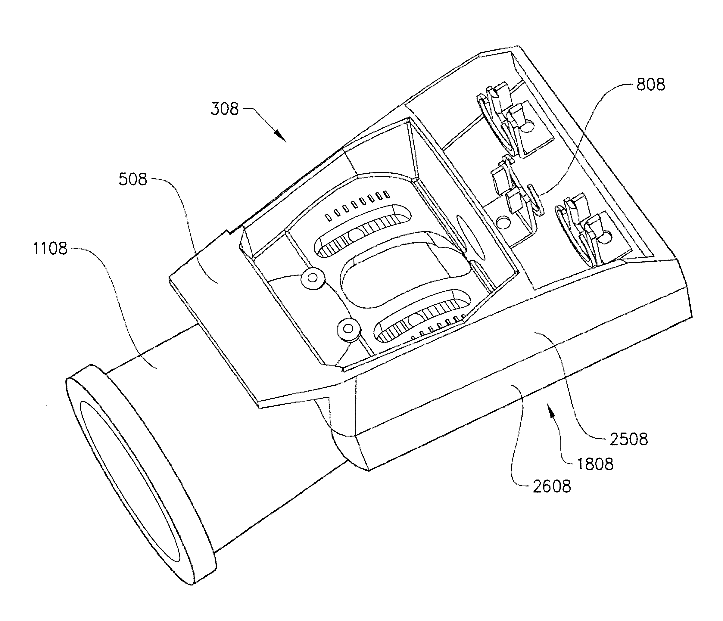
[0059]The following described examples of the invention are only to be regarded as examples and should in no way be limiting to the scope of the claims. Thus, the examples are not to be interpreted restrictively. Components may be part of the invention even if not exposed in the following figures.

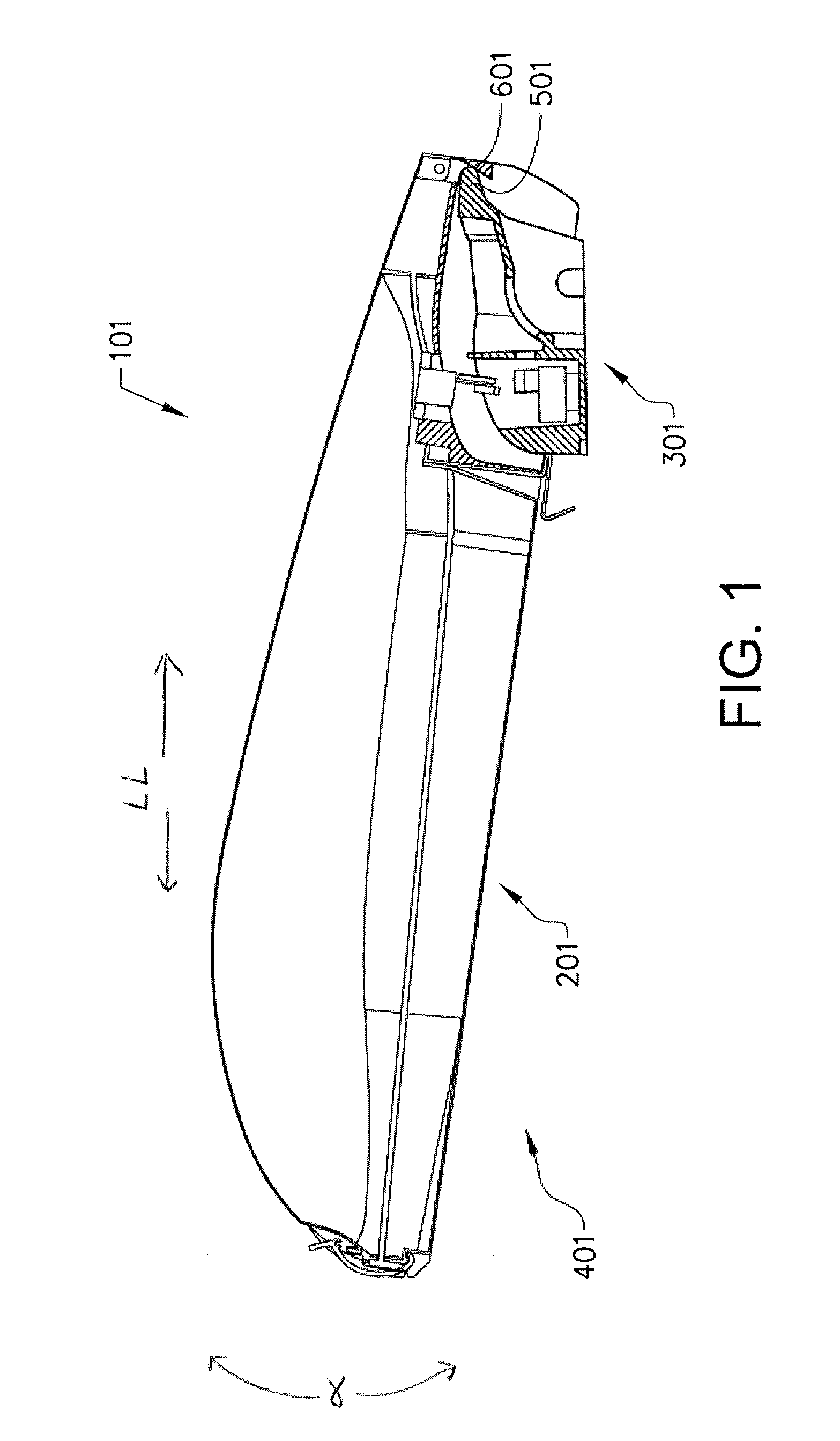
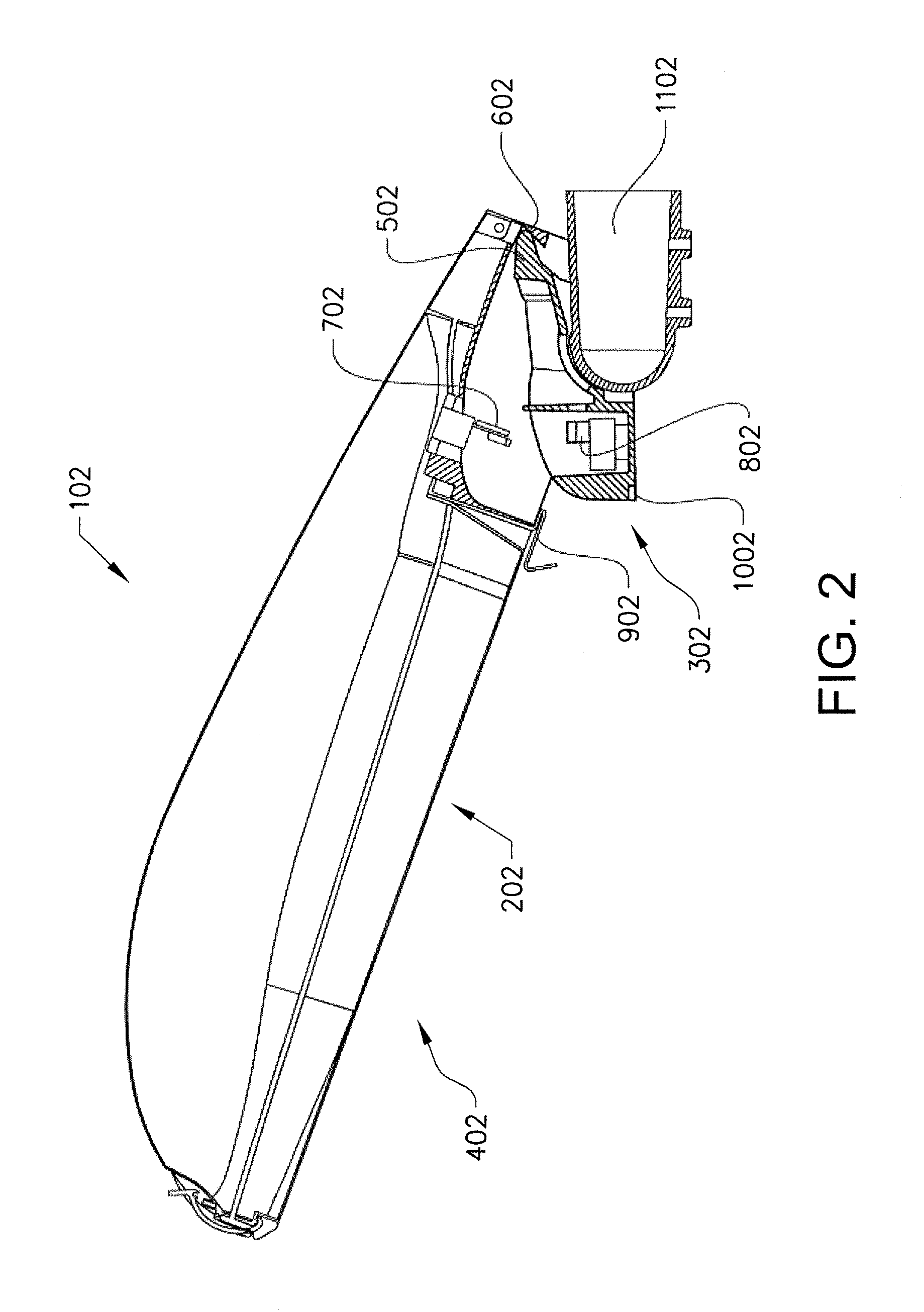
[0060]FIG. 1 shows an example of an inventive lighting device 101, comprising a lighting body 201 and a socket body 301 in cross-section. FIG. 1 shows the lighting body when in a second open position 401, where the first guiding means of the lighting body 201 and a second guiding means of the socket body 301 interact in order to guide the lighting body 201 towards the socket body 301 in elevation direction. Furthermore, FIG. 1 shows how the projecting socket part 501 of the socket body 301 interacts with the internally located contact surface 601 of the lighting body 201 and forms a point of contact around which the lighting body 201 can move in elevation direction relative to the socket bo...


PUM


Abstract

A lighting device for outdoor use comprising a lighting body and a socket body, where the lighting body comprises a lighting unit, a first electrical connection and a first locking member. The socket body comprises a second electrical connection and a second locking member, wherein the first and second electrical connections are arranged to connect to each other in a closed position in order supply the lighting unit with power. The first locking member and the second locking member are arranged for locking and unlocking the lighting body to the socket body in said closed position. The lighting body comprises a first fastening device and the socket body comprises a second fastening device, wherein the fastening devices are arranged to. The lighting body comprises a first guiding means and the socket body comprises a second guiding means, which are arranged to interact.

Description

CROSS REFERENCE TO RELATED APPLICATIONS[0001]This application is a U.S. National Phase patent application of PCT / SE2013 / 050085, filed on Jan. 31, 2013, which claims priority to Swedish Patent Application No. 1250071-6, filed on Feb. 1, 2012, and Swedish Patent Application No. 1251100-2, filed on Oct. 1, 2012, the entire contents of which are incorporated herein by reference.FIELD OF THE INVENTION[0002]The present invention relates to a lighting device for outdoor use comprising a lighting body and a socket body, where the lighting body is adapted to be easily arranged on the socket body using guiding means and fastening devices for easy mounting and dismounting.BACKGROUND OF THE INVENTION[0003]Replacement of light bulbs in street light fittings are traditionally handled by a person that is lifted to the street light fitting in a man lift or similar and by hand opens up the light fitting and next replaces the light bulb. This is problematic in several aspects.[0004]The most obvious a...

Claims


Application Information

Patent Timeline
Patent Type & Authority Applications(United States)
IPC IPC(8): F21S8/08F21V23/02F21V21/30F21V21/116F21V23/06
CPCF21S8/086F21V21/116F21W2131/103F21V21/30F21V23/023F21V23/06B25J5/007B25J15/0052B25J19/023F21V19/04F21V21/002F21V25/04F21S8/085F21V17/16F21V19/00F21W2111/02B25J15/0004
Inventor CARLEN, RIKARD
Owner STRIHL SCANDINAVIA
Learn More