Device for pumping a fluid at low flows

a technology of fluid pumping and fluid flow, which is applied in the direction of instruments, laboratory equipment, material analysis, etc., can solve the problems of reducing flow speed, undesirable dilution of samples, and affecting the flow rate, so as to increase the flow speed, increase the friction against the fluid, and improve the effect of fluid flow

Active Publication Date: 2015-02-19
ENVIC SENSE
View PDF3 Cites 0 Cited by
  • Summary
  • Abstract
  • Description
  • Claims
  • Application Information

AI Technical Summary

Benefits of technology

[0015]According to an embodiment of the invention, the surface of the cylinder is substantially smooth, i.e. the surface is not provided with any projections for increasing the friction against the fluid or for pressing or pushing away the water and thereby increase the flow speed. A smooth surface provides sufficient friction against the fluid to generate the desired vortex. It is simple and inexpensive to manufacture a cylinder with a smooth surface.
[0016]According to an embodiment of the invention, the pump comprises a drive wheel and a drive shaft fixedly mounted between the drive wheel and the cylinder, wherein the drive wheel has a substantially larger diameter than the cylinder. Such a pump is simple and inexpensive to manufacture.
[0017]A device according to the invention can advantageously be used to circulate fluid past a sensor in a measuring cell for the detection and quantification of heavy metals, such as mercury.

Problems solved by technology

A disadvantage of this pump is that it is relatively expensive.
A disadvantage of the pump shown in WO2005 / 121744 is that the flow decreases with the distance from the cylinder, resulting in an uneven flow profile, with high flow speed in the part of the channel nearest to the cylinder and a decreasing flow speed in the direction towards the opposite channel wall. FIG. 9 shows how the flow profile may look in a channel with this type of pump.
This flow profile provides a risk for sedimentation of particles in the part of the channel where the flow speed is low and can also lead to extension of the sample in the flow direction, which results in an undesirable dilution of the sample.
The location of the pump in the flow channel also constitutes a risk for formation of stationary flow vortices, so-called Couette flow.
These flow vortices provide a risk that the particles to be measured accumulate and will not pass the sensor, which in turn means that the measurement is impaired.

Method used


Image

  • Device for pumping a fluid at low flows
  • Device for pumping a fluid at low flows
  • Device for pumping a fluid at low flows

Examples


Embodiment Construction

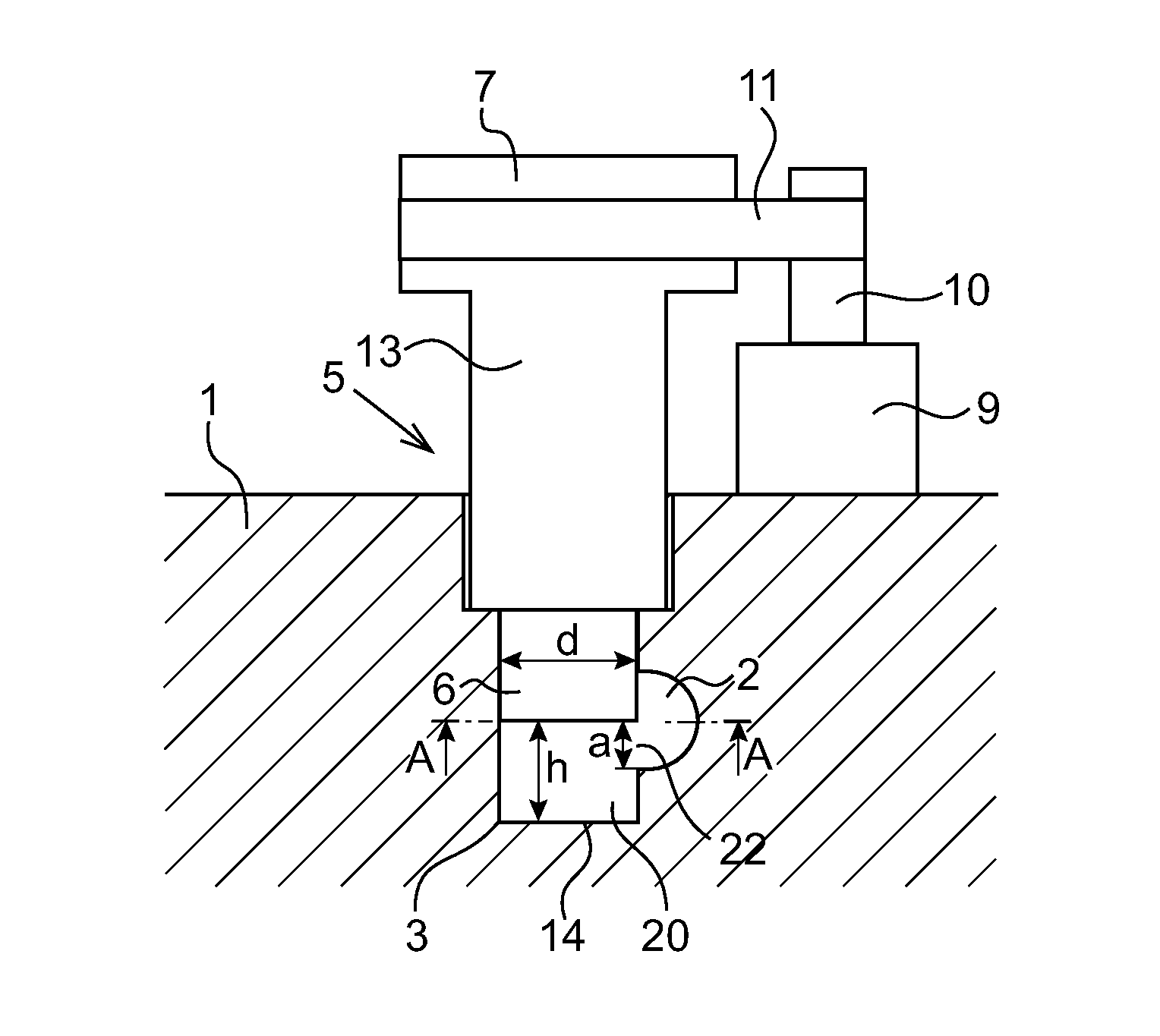
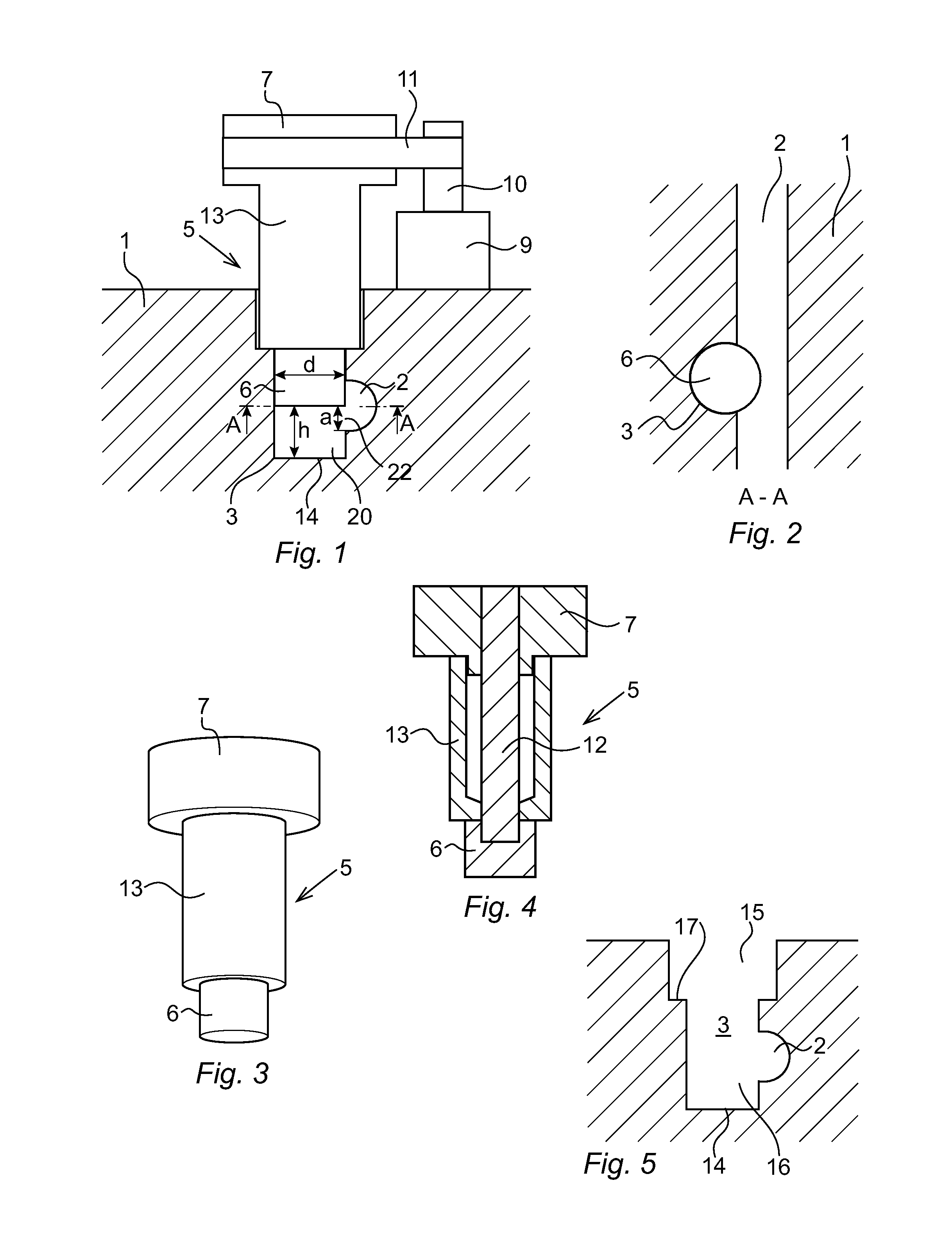
[0029]FIG. 1 shows a device for pumping fluid at low flows according to an embodiment of the invention. The device comprises a body 1 with an elongated channel 2 for the transport of fluid and a cylindrical cavity 3 disposed adjacent to the channel 2. The channel 2 is cylindrical and has a circular cross section. The cavity 3 is arranged so that the longitudinal axis of the cavity is angled relative to the longitudinal axis of the channel. The angle between the longitudinal axis of the cavity and the longitudinal axis of the channel should preferably be more than 45°. More preferably, the cavity is arranged with its longitudinal axis substantially perpendicular to the longitudinal axis of the channel.

[0030]The body 1 is preferably made of a plastic material, such as polyetheretherketone (PEEK) or acrylic plastic, but can also be made of glass. The body 1 may, for example, be part of a disposable measurement cell for detecting and / or measuring particles. The device can advantageously...


PUM


Abstract

The present invention relates to a device for pumping a fluid at low flows, comprising a body (1) including a channel (2) having a circular cross section for transportation of a fluid, and a cylindrical cavity (3) arranged in connection with the channel and with its longitudinal axis being non coplanar with the longitudinal axis of the channel, and a pump including a rotatable cylinder (6) extending into the cavity, coaxial with the cavity, with the periphery of the cylinder protruding into the channel, thereby driving the fluid in the channel by shear forces. The channel and the cylinder are both arranged at a distance from the bottom of the cavity, so as to form a cylindrical space (20) between the cylinder and the bottom of the cavity for receiving some of the driven fluid, wherein the cylinder and the cavity are arranged so that a vortex (23) is generated in the fluid in the space by the rotation of the cylinder, and an opening (22) is formed between the space and the channel, which allows the vortex generated in the space to continue into the channel. The device provides a steady and smooth flow in the channel.

Description

FIELD OF THE INVENTION[0001]The present invention relates to a device for pumping a fluid at low flows. Such a device can be used in various types of systems for pumping fluid at flows less than 100 ml / s.PRIOR ART[0002]There are many applications where small amounts of fluid has to be transported, for example, in connection with various types of measurement in a fluid, such as detecting and measuring small quantities of a certain substance, when counting cells, and measurement of the kinetics of chemical reactions. Thus, there is a need to develop small, simple, and inexpensive pumps for pumping small amounts of a fluid, in the order of less than 100 ml / s. To obtain a good reliability, it is important that the pump has as few moving parts as possible.[0003]US2006 / 0057004 shows an example of a pump that is embedded in a substrate and has a homopolar motor including a rotatable disc provided with fluid blades. The rotatable disc is placed in a cavity in the substrate and is connected ...

Claims


Application Information

Patent Timeline
Patent Type & Authority Applications(United States)
IPC IPC(8): F04D29/18F04D25/02
CPCF04D29/181F05B2250/80F04D25/02B01L3/50273F04D5/001F04B19/18F04B19/20F04B19/006G01N35/1095
Inventor GARDHAGEN, PETERGARDHAGEN, EVA-LENA
Owner ENVIC SENSE
Why Eureka
Try Eureka