Appliance for drying articles

a technology for drying articles and drying sheets, applied in drying, lighting and heating apparatus, furniture, etc., can solve problems such as microwave frequencies

Active Publication Date: 2015-02-26
WHIRLPOOL CORP
View PDF34 Cites 19 Cited by
  • Summary
  • Abstract
  • Description
  • Claims
  • Application Information

AI Technical Summary

Problems solved by technology

In dielectric heating, microwave frequencies are typically applied for cooking food items and are considered undesirable for drying l

Method used


Image

  • Appliance for drying articles
  • Appliance for drying articles
  • Appliance for drying articles

Examples


Embodiment Construction

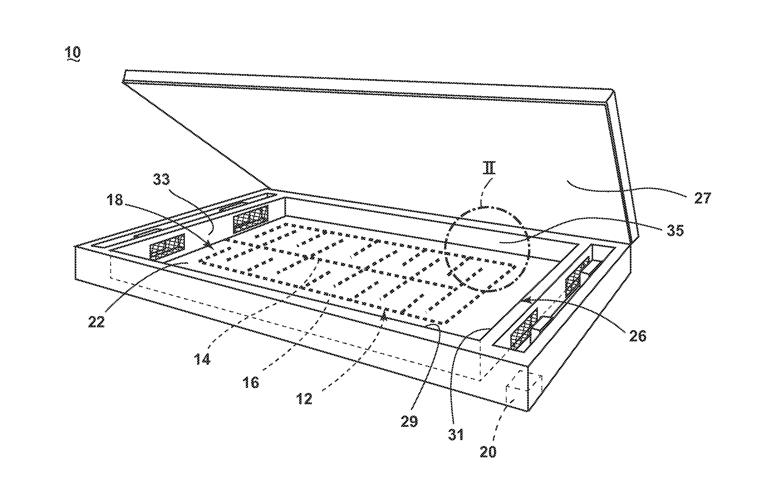
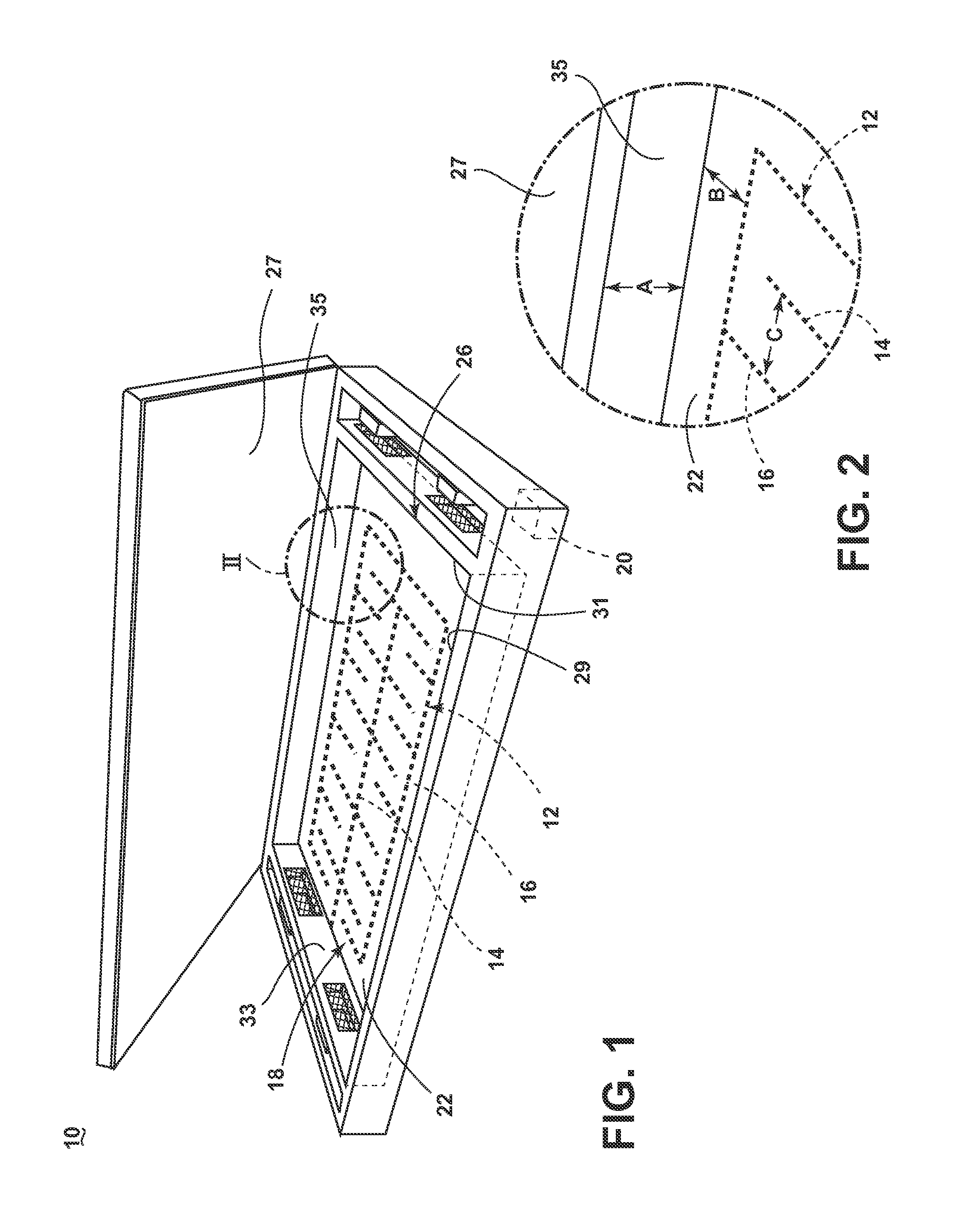
[0011]While this description may be primarily directed toward a laundry drying machine, the invention may be applicable in any environment using a radio frequency (RF) signal application to dehydrate any wet article.

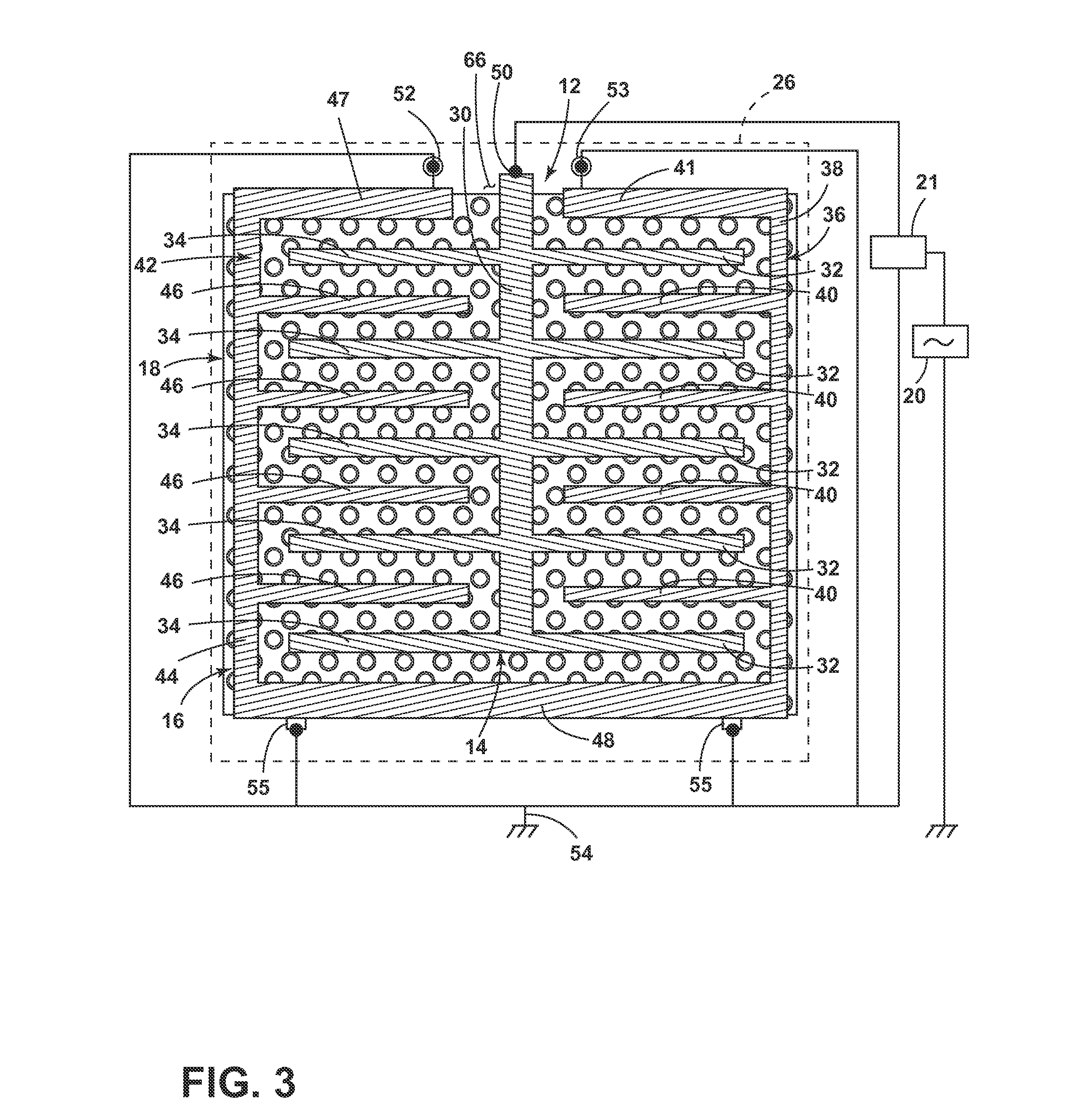
[0012]As illustrated in FIG. 1, the RF laundry drying appliance 10 includes an RF applicator 12 supplied by an RF generator 20. The RF applicator 12 includes an anode element 14 and a cathode element 16 coupled to the RF generator 20 which, upon the energization of the RF generator 20, creates an e-field between the anode and cathode. A drying surface 22, on which laundry is supported for drying, is located relative to the RF applicator 12 such that the drying surface 22 lies within the e-field. A Faraday cage 26 encloses the drying surface 22.

[0013]The drying surface 22 may be in the form of a supporting body 18, such as a non-conductive bed, having an upper surface for receiving wet laundry and which forms the drying surface 22. Preferably, the drying surface 22 is a p...


PUM


Abstract

A radio frequency (RF) laundry dryer includes, amongst other things, an RF generator, a drying surface and a Faraday cage enclosing the drying surface. The drying surface on which textiles are supported further includes an RF applicator having an anode and cathode coupled to the RF generator. At least a portion of the cathode substantially encompasses the anode to electrically shield the anode from the Faraday cage ensuring the formation of an e-field between the anode and cathode instead of the anode and the Faraday cage upon energizing the RF generator.

Description

BACKGROUND OF THE INVENTION[0001]Dielectric heating is the process in which a high-frequency alternating electric field heats a dielectric material, such as water molecules. At higher frequencies, this heating is caused by molecular dipole rotation within the dielectric material, while at lower frequencies in conductive fluids, other mechanisms such as ion-drag are more important in generating thermal energy.[0002]In dielectric heating, microwave frequencies are typically applied for cooking food items and are considered undesirable for drying laundry articles because of the possible temporary runaway thermal effects random application of the waves in a traditional microwave. Radio frequencies and their corresponding controlled and contained e-field are typically used for drying of textiles.[0003]When applying an RF electronic field (e-field) to a wet article, such as a clothing material, the e-field may cause the water molecules within the e-field to dielectrically heat, generating...

Claims


Application Information

Patent Timeline
IPC IPC(8): F26B3/34
CPCF26B3/34D06F58/266F26B3/347H05B6/54H05B6/62D06F58/10
Inventor HERMAN, MARK L.PETERMAN, GARRY L.RAJENDRAN, ARUN
Owner WHIRLPOOL CORP
Why Eureka
Try Eureka