
Devices and Methods for Remanufacturing Printer Cartridges

a printer cartridge and component technology, applied in the direction of gearing, hoisting equipment, instruments, etc., can solve the problems of damage to the drive axle, inability to reuse the drive axle, and difficulty in removing the drive axl

Inactive Publication Date: 2015-02-26
MITSUBISHI KAGAKU IMAGING
View PDF0 Cites 7 Cited by
  • Summary
  • Abstract
  • Description
  • Claims
  • Application Information

AI Technical Summary

Benefits of technology

The patent text describes an improved method and device for remanufacturing printer cartridge components by reusing used parts and attaching them to a new drum. The device includes a first portion with a drive axle engagement end and a second portion with a teeth engagement portion. The method involves engaging the drive axle engagement end with the first end of the drive axle and engaging the teeth engagement portion with one or more teeth portions in the first end of the drive axle. The device can then be rotated to release one or more pin elements from a snap fit attachment with the drum drive gear and disassemble the drum gear assembly. The technical effect of this invention is to provide a more efficient and effective way to remanufacture printer cartridge components.

Problems solved by technology

However, the drive axle may be attached to the drum drive gear in a manner that makes the drive axle difficult to remove from the drum drive gear, and when removal of the drive axle from the drum drive gear is attempted, such removal may cause damage to the drive axle, so that the drive axle could not be reused.
However, if not used carefully and properly, such known hand tools may damage the drive axle.
In particular, damage to the drive axle, such as damage to the portions of the drive axle that contact the printer, may affect or prevent reuse and remanufacturing of the used drive axle with a replacement drum drive gear and / or OPC drum cylinder portion.

Method used


Image

  • Devices and Methods for Remanufacturing Printer Cartridges
  • Devices and Methods for Remanufacturing Printer Cartridges
  • Devices and Methods for Remanufacturing Printer Cartridges

Examples


Embodiment Construction

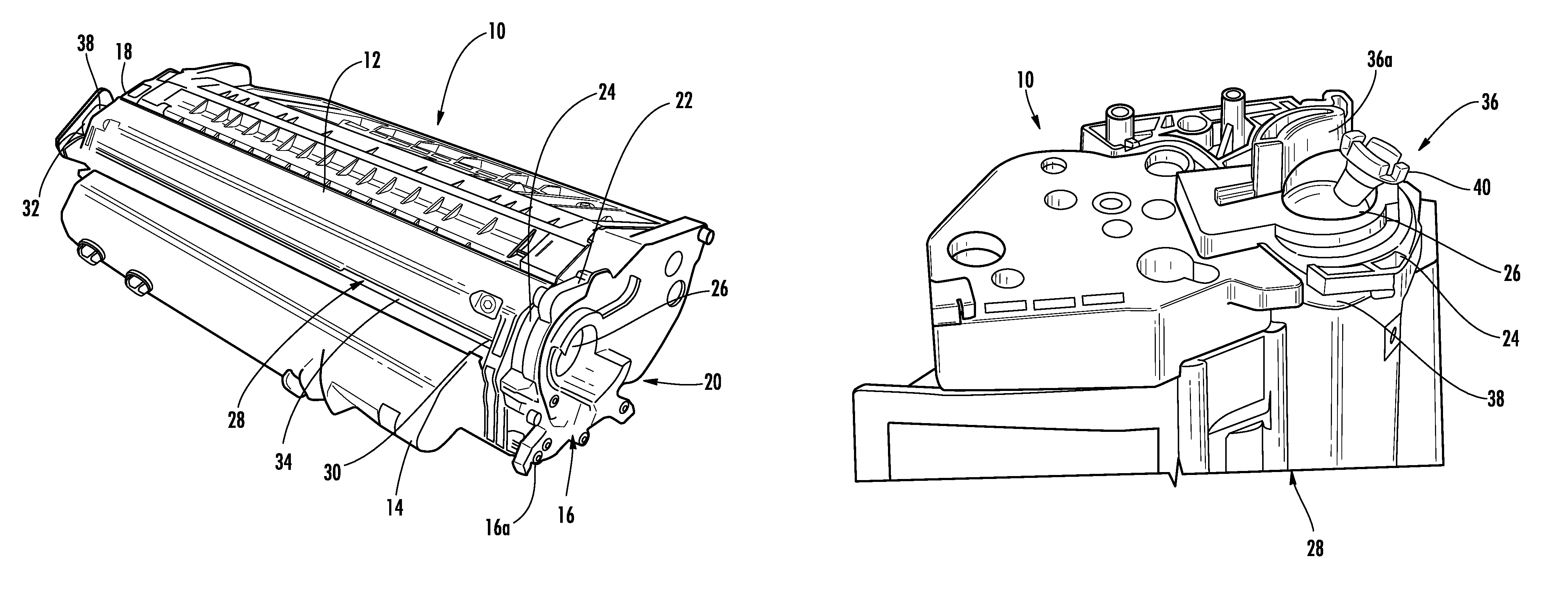
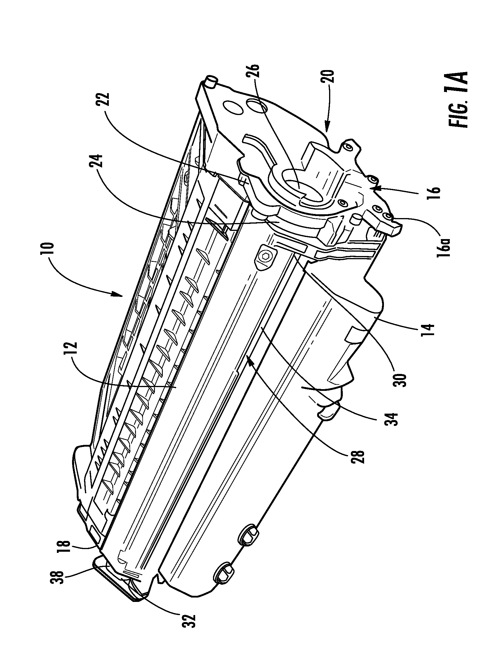
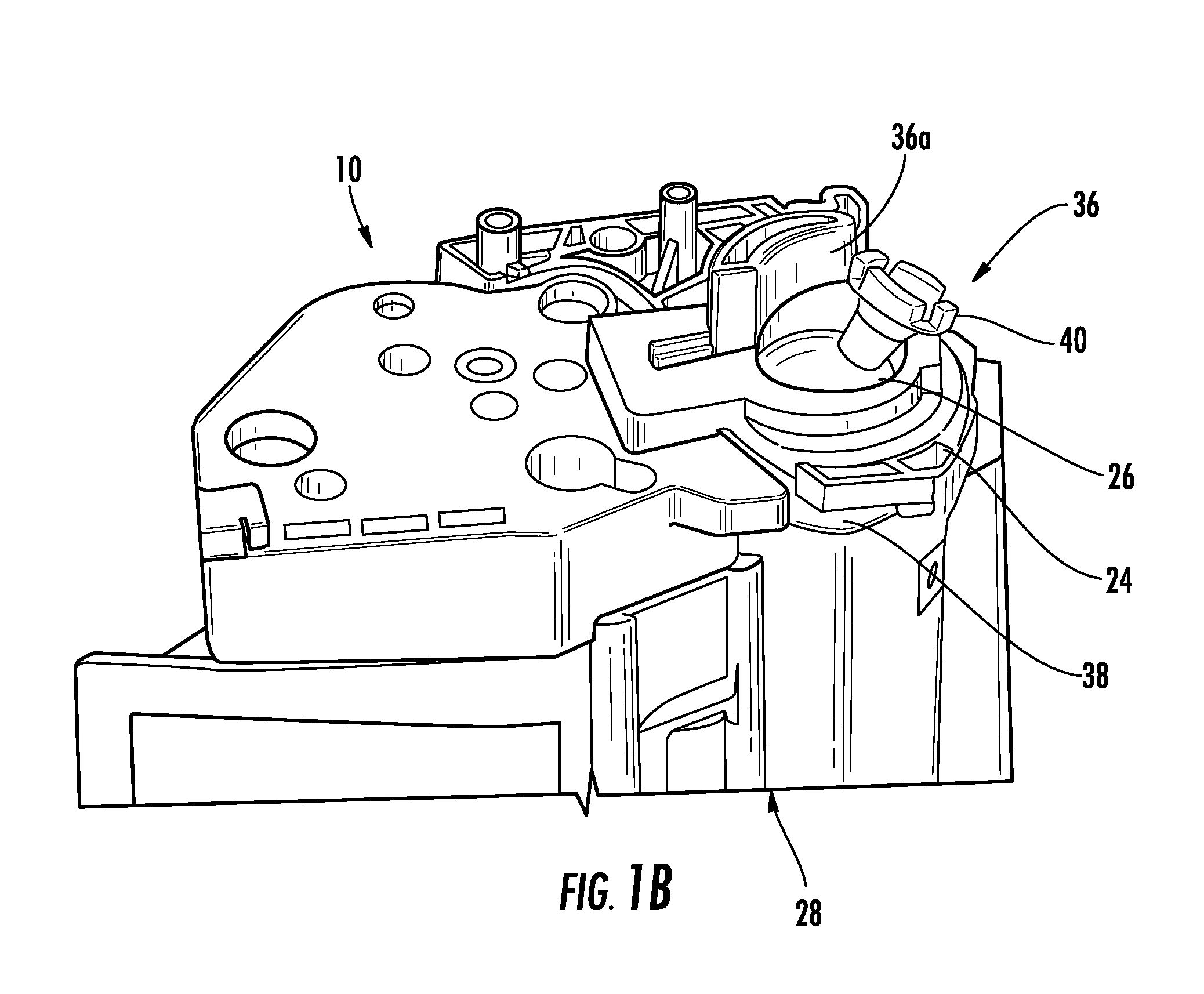
[0067]Disclosed embodiments will now be described more fully hereinafter with reference to the accompanying drawings, in which some, but not all disclosed embodiments are shown. Indeed, several different embodiments may be provided and should not be construed as limited to the embodiments set forth herein. Rather, these embodiments are provided so that this disclosure will be thorough and complete and will fully convey the scope of the disclosure to those skilled in the art. It is to be understood that other embodiments may be utilized and structural changes may be made without departing from the scope of the invention. Also, it is to be understood that the phraseology and terminology employed herein are for the purpose of description and should not be regarded as limiting.

[0068]The order in which the steps are presented below is not limited to any particular order and does not necessarily imply that they have to be performed in the order presented. It will be understood by those of...


PUM


Abstract

Devices and methods for remanufacturing a printer cartridge component are provided. The printer cartridge component is a drum gear assembly configured for attachment to an organic photoconductor (OPC) drum configured for use in a printer cartridge. The drum gear assembly has a drum drive gear and a drive axle attached to the drum drive gear. The drive axle has a first end with teeth portions. The device has a first portion having a drive axle engagement end configured to engage the drive axle. The device further has a second portion coupled to the first portion. The second portion has a teeth engagement portion to engage one or more of the teeth portions of the drive axle. The first portion and the second portion are configured for assembling and disassembling the drum gear assembly.

Description

BACKGROUND[0001]a. Field of the Invention[0002]The invention relates to devices and methods for remanufacturing printer cartridge components, and, in particular, to devices and methods for remanufacturing laser printer cartridge components by remanufacturing used organic photoconductor (OPC) flange portions of assembled OPC drum flanges and attaching or assembling such used OPC flange portions to replacement OPC drum cylinder portions.[0003]b. Background Art[0004]Printer cartridges, such as toner cartridges, are used in various electrophotographic imaging devices, such as laser printers, copiers, facsimile machines, and multifunction imaging devices. Once original equipment manufacturer (OEM) printer cartridges are used, they are often recycled and remanufactured. The process of remanufacturing a printer cartridge may include cleaning the cartridge, repairing damaged parts, replacing worn parts, reassembling with new parts, and replenishing the cartridge with toner. The process of r...

Claims


Application Information

Patent Timeline
IPC IPC(8): F16H1/10
CPCF16H1/10B41J2/17559G03G21/181G03G2215/00987Y10T74/19642Y10T29/49721Y10T29/4973
Inventor NIEDERSTADT, WILLIAM F.IIJIMA, SHINICHIISHIO, KOZOCOVARRUBIAS, EDGAR
Owner MITSUBISHI KAGAKU IMAGING
Learn More