
Conveying installation with improved energy requirements

Active Publication Date: 2015-02-26
CONTITECH TRANSPORTBANDSYSTEME GMBH
View PDF6 Cites 0 Cited by
  • Summary
  • Abstract
  • Description
  • Claims
  • Application Information

AI Technical Summary

Benefits of technology

The invention is about a conveyor system that has a lighter conveyor belt, which results in lower costs and reduced energy usage. The weight of the conveyor belt is reduced by using foamed polymer mixtures on the side walls and cleats. This change does not negatively impact the function or quality of the conveyor system.

Problems solved by technology

This high level of material needed also results in a high overall weight for the conveying belt.
The application of cleats, too, increases the overall weight of the conveying belt.

Method used


Image

  • Conveying installation with improved energy requirements
  • Conveying installation with improved energy requirements
  • Conveying installation with improved energy requirements

Examples


Embodiment Construction

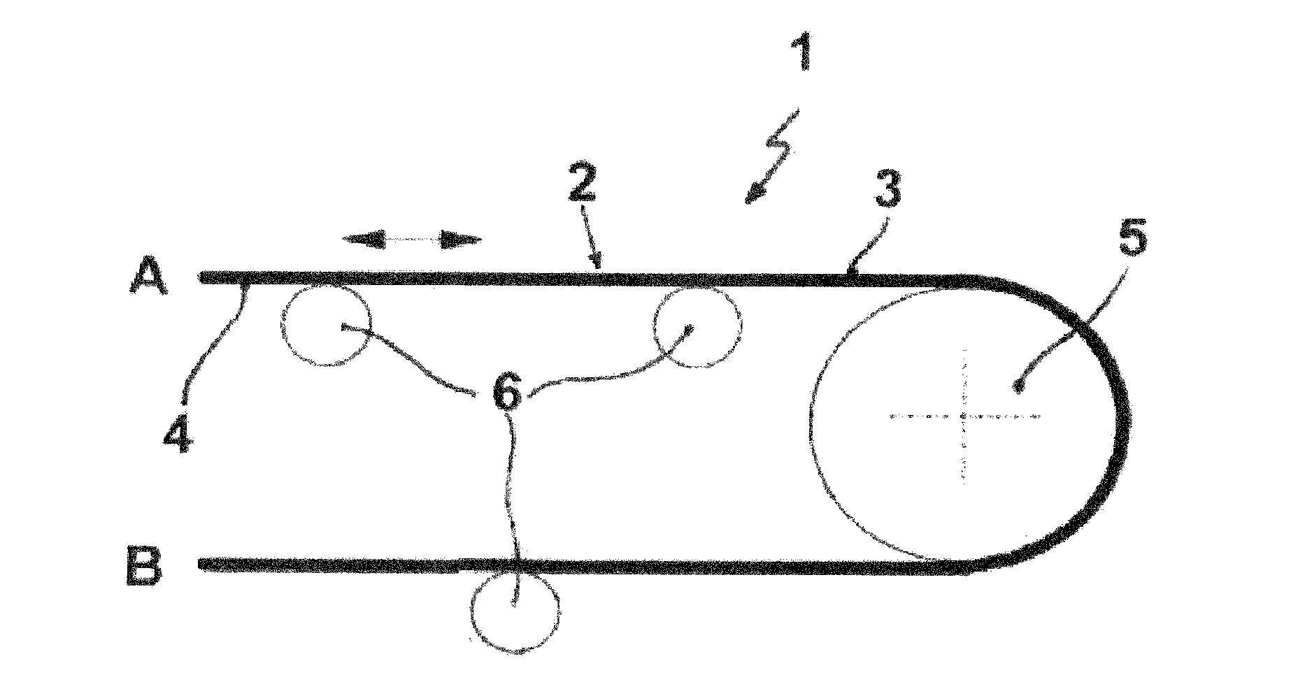
[0037]FIG. 1 shows a conveying installation 1 having a conveying belt 2, comprising a carrying-side outer sheet 3 for the conveyed material and a running-side outer sheet 4, composed in each case of a polymeric material with elastic properties, as for example of a vulcanized rubber mixture based on CR, and also having an embedded tension member, in the form of steel cables, for example. The running-side outer sheet 4 has contact with a drum 5, which may be the drive drum or reversing drum, and is also supported, within the upper strand A and lower strand B, on carrying rollers 6 in the form of a carrying-roller system. The direction in which the conveying belt 2 runs is shown by the arrow direction.

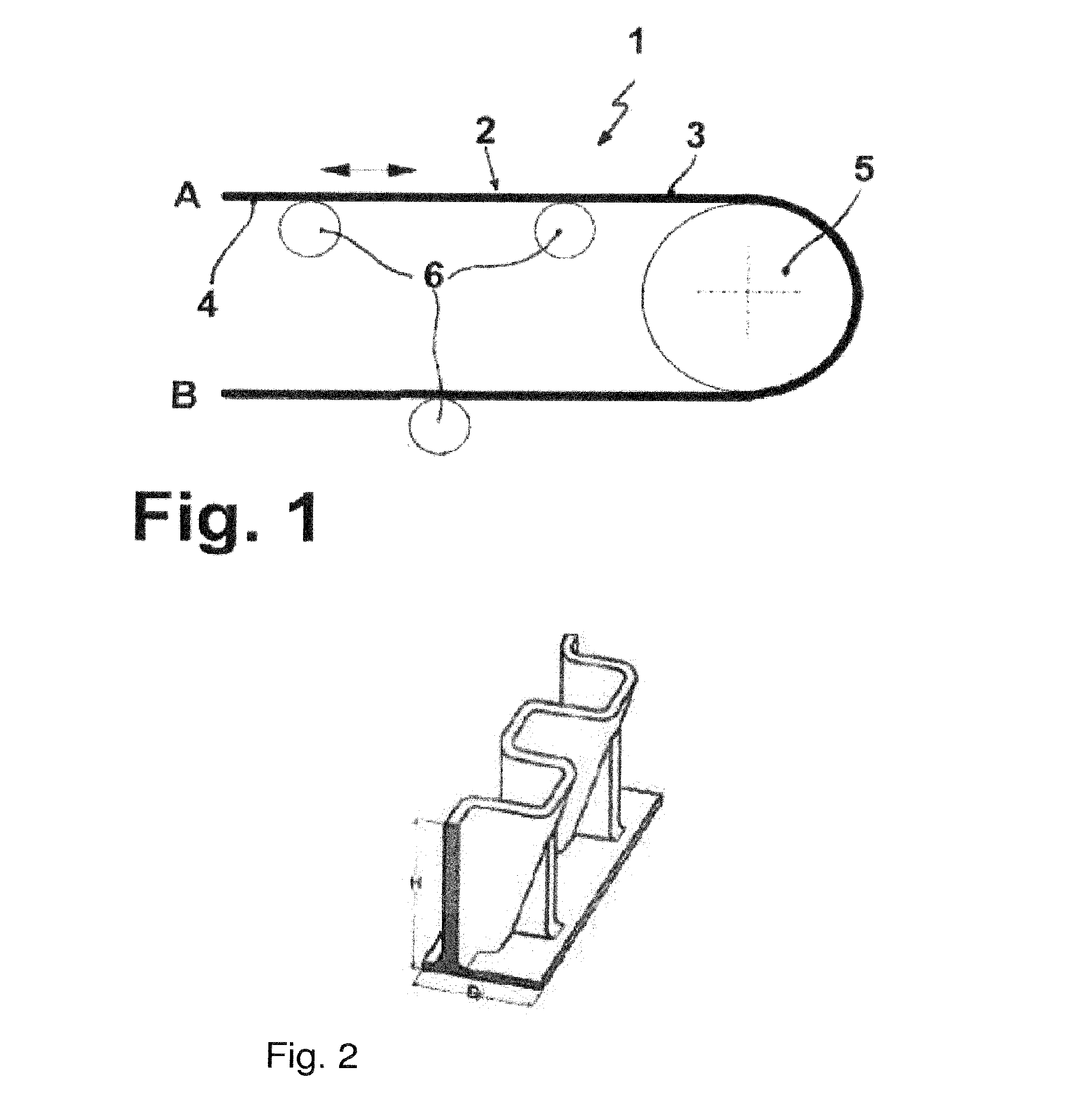
[0038]FIG. 2 shows a cross section through an undulating edge which comprises at least one foamed polymer mixture.

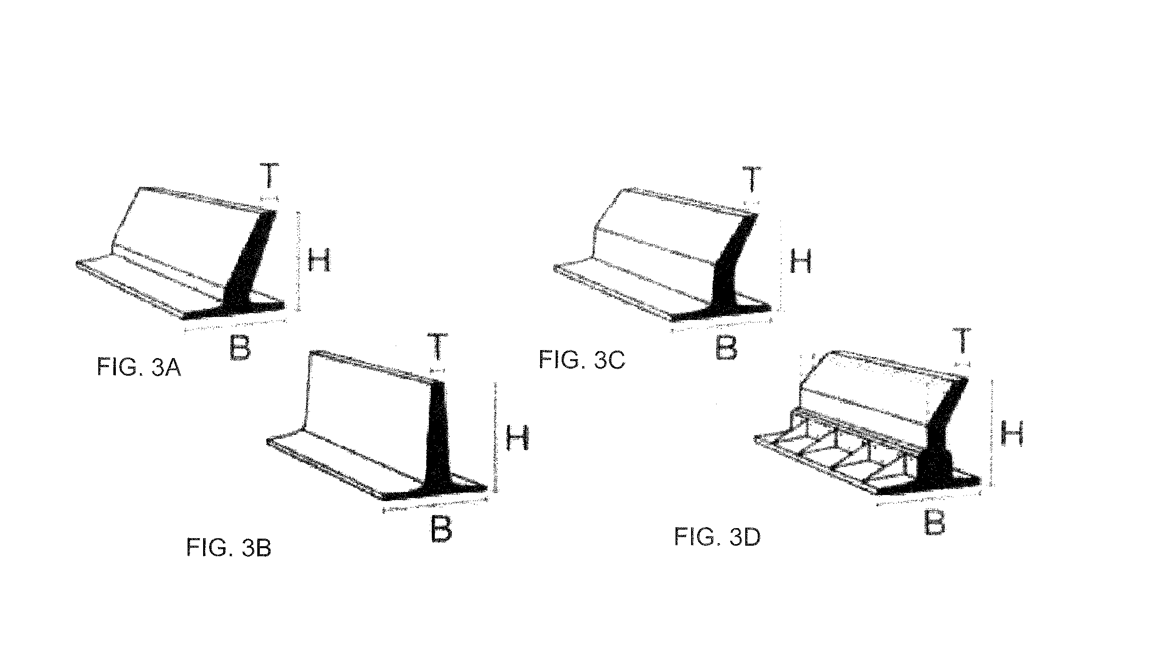
[0039]FIG. 3A shows an inclined C cleat having width B, height H, and depth T.

[0040]FIG. 3B shows a standard T cleat having width B, height H, and depth T.

[0041]FIGS. 3C and 3...


PUM


Abstract

A conveying installation has a conveying belt, comprising at least one side wall, constructed from in each case one polymer material with elastic properties, and / or at least one cleat, constructed from in each case one polymer material with elastic properties, and also having drums, load-bearing rollers and load-bearing frameworks, wherein the conveying installation forms a material-conveying upper strand, with a supply location for the conveying material, and an at least material-free lower strand. In the conveying installation at least one side wall and / or at least one cleat of the conveying belt contain / contains at least one foamed polymer mix.

Description

CROSS REFERENCE TO RELATED APPLICATIONS[0001]This application is a continuation application of international patent application PCT / EP2013 / 059096, filed May 2, 2013, designating the United States and claiming priority from German application 10 2012 103 963.1, filed May 7, 2012, and the entire content of both applications is incorporated herein by reference.FIELD OF THE INVENTION[0002]The invention relates to a conveying installation having a conveying belt comprising at least one side wall constructed from in each case at least one polymeric material with elastic properties and / or at least one cleat constructed from in each case at least one polymeric material with elastic properties, and also, furthermore, having drums, carrying rollers and having carrying structures, the conveying installation forming a materials-conveying upper strand with a charging location for the conveyed materials, and a usually materials-free lower strand. There are, however, also conveying installations w...

Claims


Application Information

Patent Timeline
IPC IPC(8): B65G15/56B65G15/28
CPCB65G15/28B65G15/56B65G15/42
Inventor THOMCZYK, ANDREAKANTOREK, FRANK
Owner CONTITECH TRANSPORTBANDSYSTEME GMBH
Learn More